Heated cleaning device

A technology for cleaning device and heating wire, applied in water heaters, fluid heaters, lighting and heating equipment, etc., can solve problems such as damage to the insulation of the heating wire, complicated assembly process of the heating wire, and expansion of the ice plug of the shell.

Pending Publication Date: 2021-06-04
CONTINENTAL AUTOMOTIVE TECH GMBH
View PDF2 Cites 0 Cited by
  • Summary
  • Abstract
  • Description
  • Claims
  • Application Information

AI Technical Summary

Problems solved by technology

[0005] The assembly process of the heating wire thus laid during manufacture proved to be very complicated
In addition, there is a risk of damage to the insulation of the heating wire by assembly tools or edges on protruding parts
[0006] Furthermore, there is a risk that the housing of such a cleaning device may be inflated by ice plugs formed therein

Method used


Image

  • Heated cleaning device
  • Heated cleaning device
  • Heated cleaning device

Examples


Embodiment Construction

[0030] figure 1

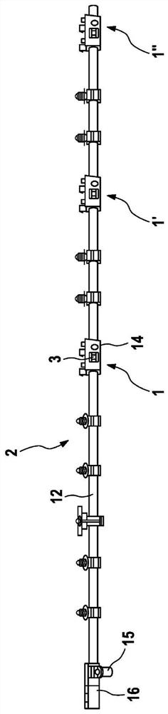
[0031] exist figure 1 In , a heated washer 2 is shown in simplified form and not to scale, which is designed as a so-called nozzle chain and is used for cleaning vehicle windows. A plurality of cleaning devices 1, 1', 1" are connected in series on a common fluid line 12. In the embodiment shown, each of the cleaning devices 1, 1', 1" has: an outer housing 14, This outer housing is non-removably connected to a vehicle part, for example to an additional part of the bonnet; and to a housing 3 which is pivotally mounted in an outer housing 14 through which the jet of cleaning fluid passes through the The window in the body 14 shoots out of the housing.

[0032] The cleaning device is supplied with cleaning fluid under pressure via a hydraulic connection 15 from a delivery device (not shown here).

[0033] A heating line supplied with electric current via the electrical connection 16 is run through the fluid line 12 and the cleaning device 1 , 1 ′, 1 ″. When t...


PUM


Abstract

The invention relates to a cleaning device (1) for a washing apparatus (2) arranged in a vehicle, comprising a housing (3) having a chamber (4) formed in the housing (3), which chamber can be filled with cleaning fluid and can be hydraulically connected to at least one spray nozzle (5) for the cleaning fluid, and having at least one heatable heating wire (6), at least part of which protrudes into the chamber (4). The aim of the invention is to obtain a high level of functional reliability even at low temperatures and to enable particularly fast and reliable deicing. This aim is achieved, according to the invention, in that a thermal conduction element (7) is arranged in the chamber (4) in order to enlarge a heat-transferring convection surface, which thermal conduction element absorbs the heat from the heating wire (6), the cleaning fluid flowing around at least some regions of the thermal conduction element, in particular around the entire thermal conduction element.

Description

technical field [0001] The invention relates to a cleaning device according to the preamble of claim 1 . Background technique [0002] Cleaning devices are known for washing systems arranged in vehicles for cleaning windows, headlights, cameras etc. with cleaning fluid. In order to effectively clean a plurality of cleaning points and / or large areas which are far apart from one another, a plurality of such cleaning devices are often connected in series in a cleaning installation to a common fluid line and form a so-called nozzle chain. At temperatures below the freezing point of the cleaning fluid, freezing may occur, whereby the ice may clog the cleaning device or may even damage the cleaning device due to its expansion. To avoid this, it is known to design the cleaning device as heated, in particular by guiding one or more heating wires through the cleaning device and heating the cleaning fluid therein. Reliable and fast deicing to restore flowability is the main challeng...

Claims


Application Information

Patent Timeline
Patent Type & Authority Applications(China)
IPC IPC(8): B60S1/48F24H1/00
CPCB60S1/488F24H1/009F24H1/102F24H1/103B60S1/487B60S1/52
Inventor H·韦策尔A·雷斯S·沙克尔R·克劳斯
Owner CONTINENTAL AUTOMOTIVE TECH GMBH
Why Eureka
Try Eureka