Far-end radial artery tourniquet and far-end radial artery hemostat

A tourniquet and radial artery technology, applied in the field of medical devices, can solve the problems of no available convenient hemostatic equipment for hemostasis, inability to accurately judge the hemostasis effect, excessive dependence on the experience of the operator, etc., achieving good fixation effect, fewer types of raw materials, and fewer instruments. effect of reserve

Pending Publication Date: 2021-06-08
D PULSE MEDICAL BEIJING CO LTD
View PDF0 Cites 1 Cited by
  • Summary
  • Abstract
  • Description
  • Claims
  • Application Information

AI Technical Summary

Problems solved by technology

However, for the distal radial artery puncture technique, because the distal radial artery puncture point is located in the hand, the surrounding hand structure is obviously tapered, resulting in that the existing radial artery hemostat products cannot be stably fixed at the puncture point, which in turn leads to There is no convenient hemostatic equipment available for posterior hemostasis, a

Method used


Image

  • Far-end radial artery tourniquet and far-end radial artery hemostat
  • Far-end radial artery tourniquet and far-end radial artery hemostat
  • Far-end radial artery tourniquet and far-end radial artery hemostat

Examples


Embodiment 1

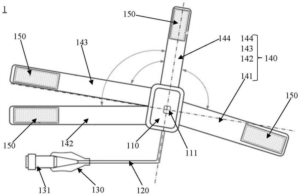
[0039] Please refer to figure 1 A distal radial artery hemostat 1 provided in this embodiment includes: an inflatable tube 120, a small air bag 130, an inflation valve 131, an inflation device and a distal radial artery tourniquet provided in this embodiment, wherein the The distal radial artery tourniquet comprises: a compression balloon 110 and a fixing band 140. The inflation valve 131 is located at the end of the small air bag 130, the distal radial artery tourniquet is connected to the small air bag 130 through the inflation tube 120, and the inflation device can be inserted into the inflation valve 131 to achieve The inflation and deflation of the compressed airbag 110.

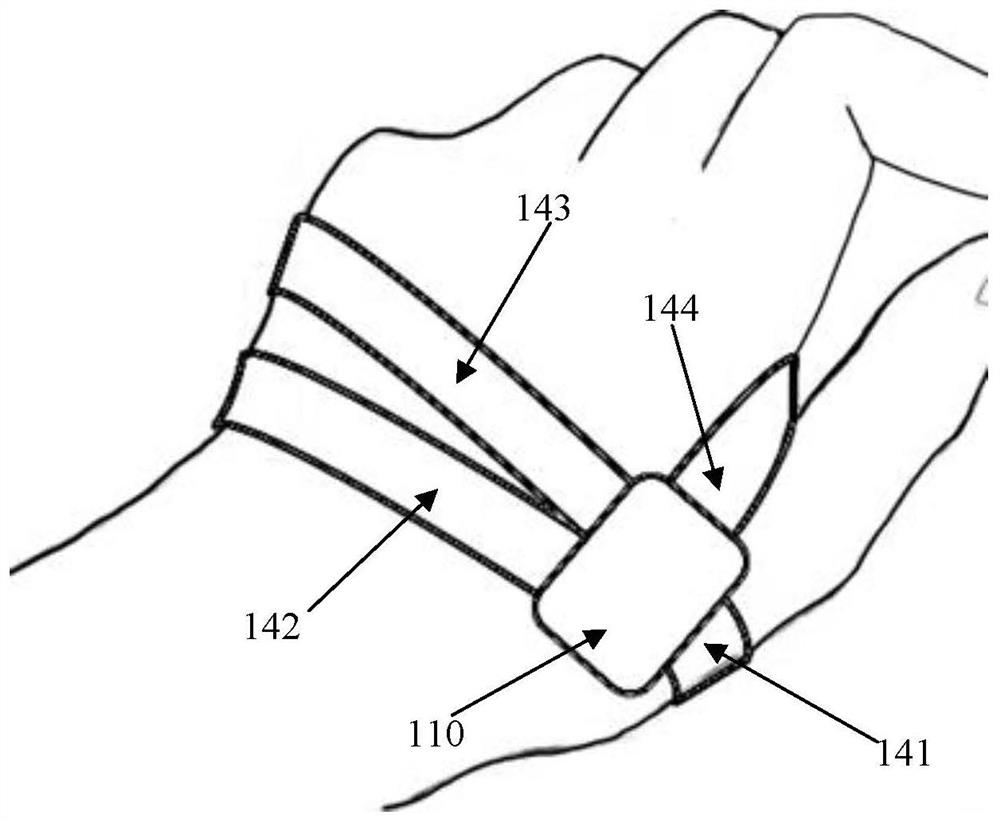
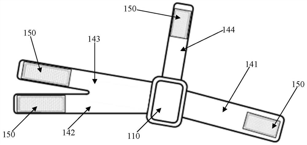
[0040] In this embodiment, the number of the fixing bands 140 in the distal radial artery tourniquet is four and the shapes are all bar-shaped, and one end of the four fixing bands 140 is sequentially connected around the compression airbag 110, each The other end of the fixing band 140 is used to con...

Embodiment 2

[0051] The main difference between the distal radial artery tourniquet provided in this embodiment and the distal radial artery tourniquet in Embodiment 1 is that there are three fixing bands. Such as Figure 5 As shown, the three fixing straps are distributed clockwise as the fifth fixing strap 145, the sixth fixing strap 146, and the seventh fixing strap 147, wherein the sixth fixing strap 146 includes a first sub-fixing strap 1461, a second The sub-fixing belt 1462 and the connecting part 1463, the shape of the fifth fixing belt 145 and the seventh fixing belt 147 are strips. Such as Figure 5 As shown, the connecting portion 1463 is used for connecting the first fixing belt 1461 and the second sub-fixing belt 1462 , and is also used for connecting the compression airbag 110 .

[0052] In use, the fifth fixing strap 145 can be connected to the first sub-fixing strap 1461, and the second sub-fixing strap 1462 can be connected to the seventh fixing strap 147; The fixing be...


PUM


Abstract

The invention provides a far-end radial artery tourniquet and a far-end radial artery hemostat. The far-end radial artery tourniquet and the far-end radial artery hemostat are used for compression hemostasis of puncture points after far-end radial artery paracentesis, wherein the far-end radial artery tourniquet comprises a compression air bag and at least three fixing bands, one ends of the at least three fixing bands are sequentially connected to the periphery of the compression air bag, the other end of each fixing band is provided with a connecting piece which is used for being connected with other fixing bands to fix the compression air bag during the compression hemostasis. According to the far-end radial artery tourniquet and the far-end radial artery hemostat, during the compression hemostasis, the fixing bands can conform to a hand shape to fix the compression air bag, the fixing effect is good, and a patient wears the far-end radial artery tourniquet and the far-end radial artery hemostat comfortably.

Description

technical field [0001] The invention belongs to the technical field of medical devices, in particular to a distal radial artery tourniquet and a distal radial artery hemostat. Background technique [0002] The distal radial artery puncture technique is a new interventional puncture technique developed in recent years. It is a new interventional approach and an effective supplement to the conventional approach. According to the clinical practice in recent years, this technique has been used in some cases (including but not limited to: when conventional radial artery puncture fails (spasm, hematoma, etc.), radial artery pulse is unclear during the second interventional operation, bilateral radial artery When dealing with CTO, or acute and chronic occlusion of the radial artery), it is more operable and safer than the traditional radial artery puncture; at the same time, because the patient's hand can be naturally placed on the abdomen during the operation, it brings better com...

Claims


Application Information

Patent Timeline
IPC IPC(8): A61B17/135
CPCA61B17/135A61B2017/12004
Inventor 王海峰
Owner D PULSE MEDICAL BEIJING CO LTD
Why Eureka
Try Eureka