Micro-reactor, parallel efficient micro-reactor and application of parallel efficient micro-reactor
A micro-reactor, reactor shell technology, applied in chemical/physical/physical-chemical reactors, chemical instruments and methods, chemical/physical/physical-chemical processes, etc. Small contact area, etc.
- Summary
- Abstract
- Description
- Claims
- Application Information
AI Technical Summary
Problems solved by technology
Method used
Image
Examples
Embodiment 1
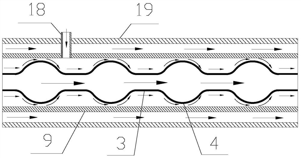
[0029] This embodiment discloses a microreactor, such as figure 1 As shown, it includes an outer tube 19, a reaction tube 9 and an inner tube 3 that are sequentially set from the outside to the inside, wherein the inner tube 3 has Karman vortex generation parts 4 that are arranged at intervals along its length direction, and the mixing tube 18 passes through the outer tube. Pipe 19 is also communicated with reaction tube 9; and the position that mixing tube 18 is connected with reaction tube 9 is positioned between two Karman vortex generation parts 4, and near the previous Karman vortex generation part 4; material A flows through reaction tube 9 and the space between the inner tube 3, the material B enters the space between the reaction tube 9 and the inner tube 3 through the mixing tube 18, and mixes with the material A. The working principle and advantages of the present invention are: the material A flows through the space between the reaction tube 9 and the inner tube 3 a...
Embodiment 2
[0033] This embodiment discloses a microreactor, such as Image 6 As shown, the reaction tube 9 is a microporous membrane tube, and the microporous membrane tube is configured with tubular micropores 20 communicated with the internal space of the reaction tube 9 at intervals along its length direction. Between the street generation part 4, the material A flows between the reaction tube 9 and the inner tube 3, the material B flows between the outer tube 19 and the reaction tube 9, and the material B enters the inside of the reaction tube 9 through the tubular micropore part 20 and is connected with The material A forming the Karman vortex street phenomenon is mixed, the cooling medium A flows through the inside of the inner tube 3 , and the cooling medium B flows through the outside of the outer tube 19 . The advantage of this embodiment is that: the tubular microporous part 20 plays a dispersing role, which further strengthens the mixing; the material B enters in the form of s...
Embodiment 3
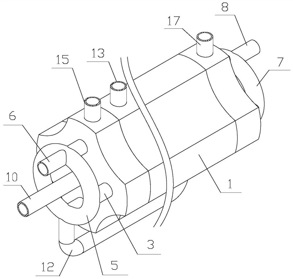
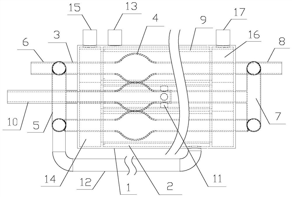
[0036] This embodiment discloses a parallel high-efficiency microreactor, such as Figure 2-5 As shown, it includes a plurality of inner tubes 3 and a plurality of reaction tubes 9 respectively sleeved outside the plurality of inner tubes 3 . Wherein, a plurality of reaction tubes 9 are built in the reactor shell 1, the cooling medium flows through the inner tubes 3 and the reactor shell 1 respectively, and the material A enters each branch pipe 11 through the first feed pipe 10 respectively. The space between the reaction tubes 9 and the corresponding inner tubes 3 , the material B enters the space between each reaction tube 9 and the corresponding inner tubes 3 through the second material tube 15 . Working principle and advantage of the present invention are: the present invention is based on the parallel microreactor formed by above-mentioned a kind of microreactor, and its difference is that the outer tube 19 of above-mentioned microreactor is replaced by reactor housing 1, ...
PUM
 Abstract
Description
Claims
Application Information
 - R&D
- Intellectual Property
- Life Sciences
- Materials
- Tech Scout
- Unparalleled Data Quality
- Higher Quality Content
- 60% Fewer Hallucinations
Browse by: Latest US Patents, China's latest patents, Technical Efficacy Thesaurus, Application Domain, Technology Topic, Popular Technical Reports.
© 2025 PatSnap. All rights reserved.Legal|Privacy policy|Modern Slavery Act Transparency Statement|Sitemap|About US| Contact US: help@patsnap.com


