Square metal punching equipment
A punching and metal technology, which is applied in the field of square metal punching equipment, can solve the problems of iron filings flying, low degree of automation, workers' health damage, etc., and achieve the effect of preventing displacement, preventing excessive temperature, and precise punching operation
- Summary
- Abstract
- Description
- Claims
- Application Information
AI Technical Summary
Problems solved by technology
Method used
Image

Examples
Embodiment 1
[0071] A square metal punching equipment such as figure 1 As shown, it includes a base 1, a servo motor 2, a propulsion mechanism 3 and a punching mechanism 4, a servo motor 2 is provided on the front side of the base 1, a propulsion mechanism 3 is provided on the left side of the base 1, and a propulsion mechanism 3 is provided between the base 1 and the propulsion mechanism 3. There are punching mechanism 4.
[0072]When people need to punch the material, the material is placed in the propulsion mechanism 3, the servo motor 2 is started, the propulsion mechanism 3 and the punching mechanism 4 start to operate, the propulsion mechanism 3 transmits the material to the punching mechanism 4, and the punching The mechanism 4 punches the material, and after the punching of the material is completed, the servo motor 2 is turned off, and the propulsion mechanism 3 and the punching mechanism 4 stop operating.
Embodiment 2
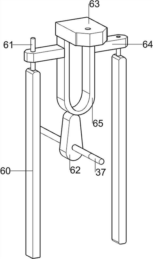
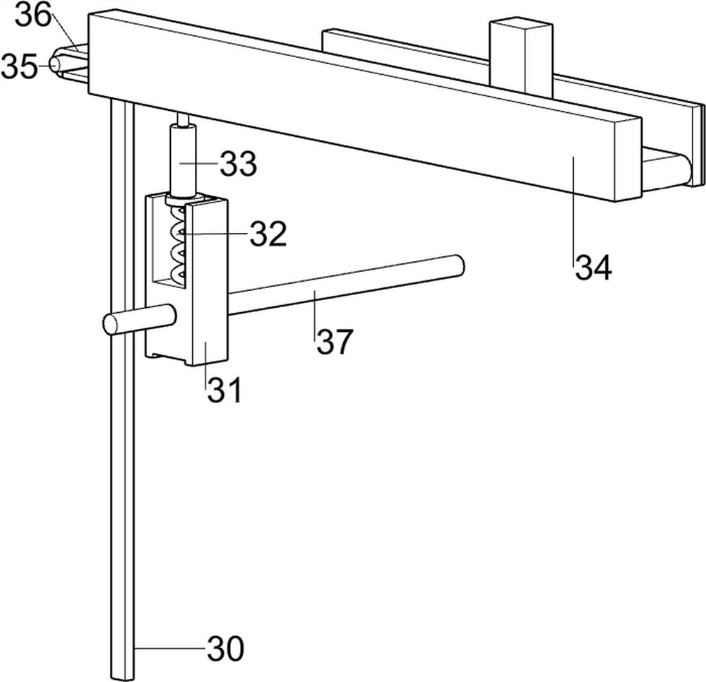
[0074] On the basis of Example 1, such as figure 2 As shown, the propulsion mechanism 3 includes a first support column 30, a slide rail 31, a first spring 32, a toggle lever 33, a baffle plate 34, a rotating lever 35 and a conveyor belt 36, and the front and rear sides of the left part of the base 1 are provided with stoppers. plate 34, the middle part of the base 1 is provided with a first support column 30, and a rotating rod 35 is rotatably connected between the baffle plate 34 and the first supporting column 30, and a conveyor belt 36 is connected between the rotating rod 35, and the output shaft of the servo motor 2 A first rotating shaft 37 is arranged on the top, and a slide rail 31 is arranged on the first rotating shaft 37. A toggle lever 33 is slidably connected to the slide rail 31, and a first spring 32 is connected between the bottom of the toggle lever 33 and the slide rail 31.
[0075] When people need to punch the material, the material is placed on the conve...
Embodiment 3
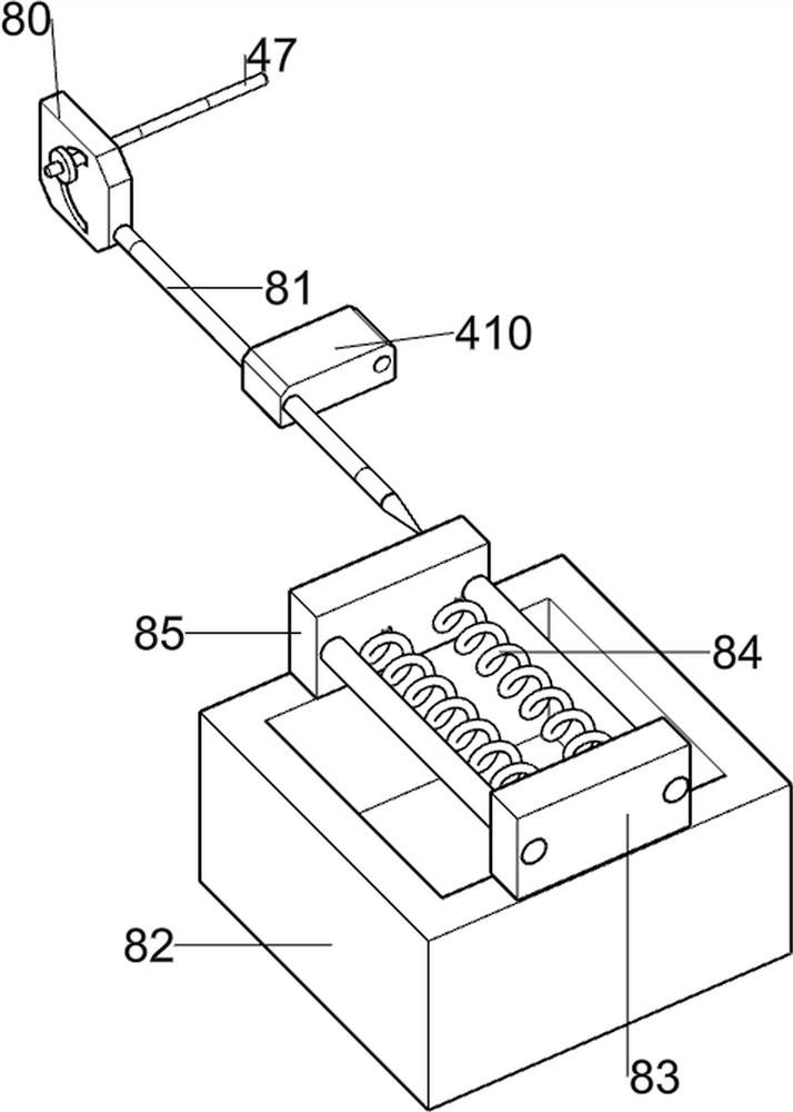
[0077] On the basis of Example 2, such as Figure 3 to Figure 8 As shown, the punching mechanism 4 includes a rotating rod 41, a transmission assembly 42, a first support block 43, a gear set 44, a second rotating shaft 45, a disc 46, a round rod 47, a first wedge block 48, and a puncher 49. , double-hole fixed block 410 and the second support block 411, the left front side of the base 1 front is provided with the second support block 411, the second support block 411 rear is rotatably connected with the second rotating shaft 45, the left rear side of the base 1 front A first support block 43 is provided, and a rotating rod 41 is connected to the first supporting block 43 in a rotatable manner. A gear set 44 is connected between the rotating rod 41 and the second rotating shaft 45. Between the rear part of the rotating rod 41 and the first rotating shaft 37 The transmission assembly 42 is connected, the second rotating shaft 45 is provided with a disk 46, the eccentric positio...
PUM
 Abstract
Description
Claims
Application Information
 - R&D Engineer
- R&D Manager
- IP Professional
- Industry Leading Data Capabilities
- Powerful AI technology
- Patent DNA Extraction
Browse by: Latest US Patents, China's latest patents, Technical Efficacy Thesaurus, Application Domain, Technology Topic.
© 2024 PatSnap. All rights reserved.Legal|Privacy policy|Modern Slavery Act Transparency Statement|Sitemap