
Automatic bag making machine

An automatic bag making machine technology, applied in bag making operations, flexible container manufacturing, paper/cardboard containers, etc., can solve the problems of low production efficiency, achieve the effects of improving production efficiency, good applicability, and reducing waste

Active Publication Date: 2021-12-14
深圳市品创源实业有限公司
View PDF0 Cites 0 Cited by
  • Summary
  • Abstract
  • Description
  • Claims
  • Application Information

AI Technical Summary

Problems solved by technology

[0004] In view of the above-mentioned related technologies, the inventor believes that in the actual production process, it is necessary to carry out bronzing operations on the packaging bags one by one, and there is a situation of low production efficiency

Method used


Image

  • Automatic bag making machine
  • Automatic bag making machine
  • Automatic bag making machine

Examples


Embodiment 1

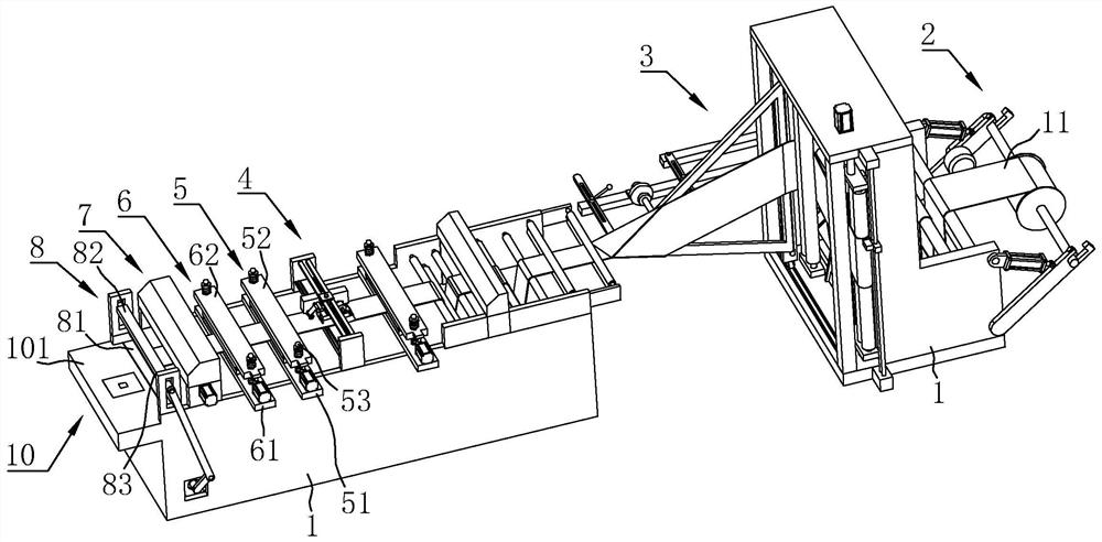
[0053] The embodiment of the present application discloses an automatic bag making machine.

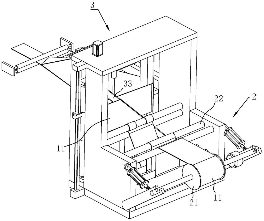
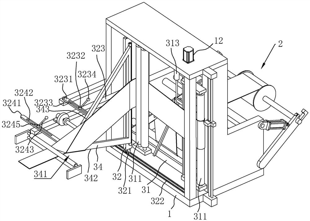
[0054] refer to figure 1 , an automatic bag making machine includes a frame 1 and a discharging mechanism 2, a half-folding mechanism 3, a bronzing mechanism 4, a heat-sealing mechanism 5, a cooling mechanism 6, a driving mechanism 7, and a cutting mechanism arranged in sequence along the length direction of the rack 1. 8. Receiving mechanism 10; the raw material belt 11 is a plastic film belt, and the raw material belt 11 is continuously transported forward under the action of the driving mechanism 7 to complete the processing of each process. Complete the folding of the raw material belt 11 in the width direction, and then realize the hot stamping logo pattern on the surface of the raw material belt 11 through the hot stamping mechanism 4. After the hot stamping is completed, the heat sealing mechanism 5 is heat-sealed to form a spaced storage cavity in the raw material, and the sto...

Embodiment 2

[0074] The embodiment of the present application discloses an automatic bag making machine.

[0075] refer to Figure 9 , the main difference from Embodiment 1 is that three heat-sealing mechanisms 5 are arranged at intervals along the length direction of the rack 1, and multiple heat-sealing mechanisms 5 can be selectively selected according to the needs of different products, and the heat-sealing mechanism 5 and the cooling mechanism 6 are both slidably connected to the rack 1 along the length direction of the rack 1. In specific use, the distance from the cooling mechanism 6 to the material cutting mechanism 8 and the distance from the heat sealing mechanism 5 to the material cutting mechanism 8 are the width of the plastic bag. That is, by adjusting the positions of the heat sealing mechanism 5 and the cooling mechanism 6 before use, so that the cooling mechanism 6 can be accurately cooled to the heat seal formed by the heat seal, and the subsequent cutting mechanism 8 can...


PUM


Abstract

This application relates to an automatic bag-making machine, which includes a frame and a driving mechanism. Along the length direction of the frame, a discharging mechanism, a folding mechanism, a heat-sealing mechanism, a material cutting mechanism and a material receiving mechanism are sequentially arranged. A bronzing mechanism is arranged in front of the feeding mechanism, and the bronzing mechanism includes a machine body, a feeding assembly for unwinding hot stamping foil, a pressing assembly and a receiving assembly for winding hot stamping foil, and the pressing assembly includes a hot platen and a drive The driving part drives the hot stamping foil of the hot platen to touch the raw material belt; the raw material belt passes through the bronzing mechanism before passing through the cutting mechanism, and the hot stamping foil is embossed on the raw material belt by means of the hot pressing plate of the pressing component The hot stamping logo is formed on the top, and then cut by the material cutting mechanism to form bags one by one. When hot stamping, there is no need to operate the bags one by one, which can effectively improve production efficiency, and the hot stamping mechanism has a receiving component, which can control the hot stamping foil. Waste materials are collected in time.

Description

technical field [0001] The present application relates to the field of bag making equipment, in particular to an automatic bag making machine. Background technique [0002] The bag making machine belongs to the equipment for manufacturing various plastic packaging bags, which can realize the mass production of plastic packaging bags. The relevant bag making machine mainly includes a frame and a driving mechanism for conveying the raw material belt. The raw material belt is usually a plastic film, and has a folding mechanism, a heat sealing mechanism, a material cutting mechanism and a material receiving mechanism in sequence along the conveying direction. The raw material tape is first folded in half by the folding mechanism, then heat-sealed by the heat-sealing mechanism, and finally cut by the cutting mechanism and collected at the receiving mechanism. [0003] However, in the actual production process, some packaging bags need to be printed with metal logos on the surfac...

Claims


Application Information

Patent Timeline
Patent Type & Authority Patents(China)
IPC IPC(8): B31B70/00B31B70/36B31B70/88B31B70/10B31B155/00
CPCB31B70/005B31B70/006B31B70/36B31B70/88B31B70/10B31B2155/001
Inventor 邵浩洋李庆亮
Owner 深圳市品创源实业有限公司
Learn More