River drainage pipe dredging device

A technology for dredging devices and drain pipes, which is applied to water supply devices, cleaning sewer pipes, waterway systems, etc., can solve problems such as high labor intensity, difficult operation, and damage to drain pipes, and achieve the effect of rapid dredging and dredging

Inactive Publication Date: 2021-06-08
广州联汇技术服务有限公司
View PDF0 Cites 0 Cited by
  • Summary
  • Abstract
  • Description
  • Claims
  • Application Information

AI Technical Summary

Problems solved by technology

[0003] In the prior art, manual dredging is mainly used, which is labor-intensive and difficult to operate, and may cause damage to the drainage pipe due to operational errors. Now there is an urgent need for a river drainage pipe dredging device

Method used


Image

  • River drainage pipe dredging device
  • River drainage pipe dredging device
  • River drainage pipe dredging device

Examples


Embodiment 1

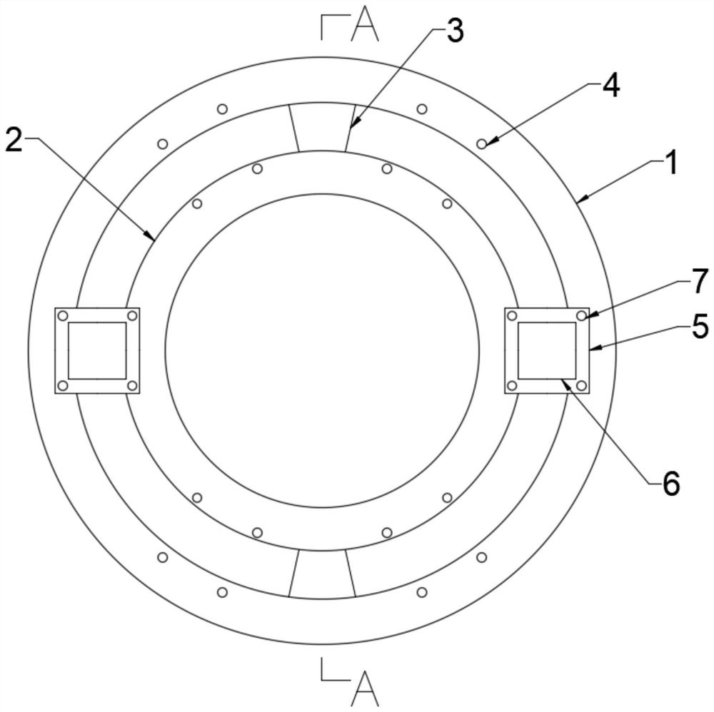
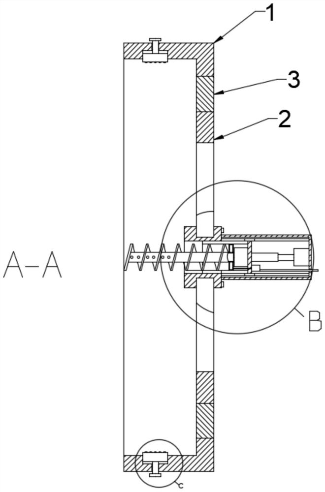
[0023] see Figures 1 to 5 In the embodiment of the present invention, a dredging device for a river drainage pipe includes a fixed outer ring 1, a limit inner ring 2 and a mounting plate 5, the inner ring of the fixed outer ring 1 and the outer ring of the limit inner ring 2 Through the fixed connection of the connecting plate 3, two annular tracks are formed between the inner ring of the fixed outer ring 1 and the outer ring of the limiting inner ring 2, and the mounting plate 5 is slidingly matched with the fixed outer ring 1 and the limiting inner ring 2, The fixed outer ring 1 is in sliding fit with the drain pipe, the box body 6 is fixedly installed on the mounting plate 5, the inner side of the fixed outer ring 1 and the outer side of the limit inner ring 2 are provided with first threaded holes 4, four. The first threaded hole 4 can determine a fixed dredging position. The mounting plate 5 is threaded to install a limit screw 7 in the circumferential direction. 5. The...

Embodiment 2

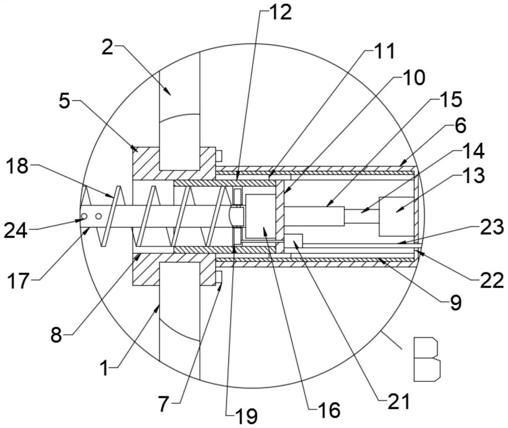
[0027] see Figures 1 to 5 , in the embodiment of the present invention, the side of the push plate 10 away from the box body 6 is fixedly installed with a guide installation pipe 12, and the guide installation pipe 12 is slidably matched with the through groove 8, which can ensure that the rotating components on the push plate 10 are in the There is no deflection when pushed out by the telescopic assembly, the second motor 16 is fixedly installed on the push plate 10, the output end of the second motor 16 is fixedly installed with a rotating shaft 17, and the outer side of the rotating shaft 17 is fixedly installed with a rotating shaft 17. Helical blade 18, the helical blade 18 rotates and cooperates with the guide installation pipe 12, the helical blade 18 can lead out the sludge in the drainage pipe while rotating, and the rotation cooperation of the helical blade 18 and the guide installation pipe 12 can reduce the rotation shaft 17 and Shaking of the helical blade 18 dur...


PUM


Abstract

The invention discloses a river drainage pipe dredging device. The river drainage pipe dredging device comprises a fixed outer ring, a limiting inner ring and a mounting plate, wherein an inner ring of the fixed outer ring is fixedly connected with an outer ring of the limiting inner ring through a connecting plate; the mounting plate is in sliding fit with the fixed outer ring and the limiting inner ring; the fixed outer ring is in sliding fit with a drainage pipe; a box body is fixedly mounted on the mounting plate; first threaded holes are formed in the inner side of the fixed outer ring and the outer side of the limiting inner ring; limiting screws are rotatably mounted on the mounting plate in a circumferential direction through threads; the limiting screws are in threaded rotation fit with the first threaded holes; and a dredging assembly is arranged in the box body. The mounting plate is mounted and fixed at a plurality of positions and the dredging assembly in the box body is matched, so that small-scale dredging and multi-position cleaning can be carried out at the same time; and rapid dredging and dredging are carried out under the condition that a drainage pipe structure is not damaged.

Description

technical field [0001] The invention relates to the technical field of river treatment, in particular to a desilting device for a river drainage pipe. Background technique [0002] River dredging generally refers to the management of the river, which is a water conservancy project. Water conservancy project is a project built to control and allocate natural surface water and groundwater to achieve the purpose of eliminating harm and benefiting, also known as water project. Water is an indispensable and valuable resource for human production and life, but its natural existence. The state does not fully meet the needs of human beings. Only by building water conservancy projects can we control water flow, prevent flood disasters, and adjust and distribute water to meet the needs of people's life and production for water resources. Water conservancy projects need to build dams, embankments, Different types of hydraulic structures such as spillways, sluice gates, intakes, channe...

Claims


Application Information

Patent Timeline
Patent Type & Authority Applications(China)
IPC IPC(8): E03F9/00
CPCE03F9/00E03F9/005E03F9/007
Inventor 吕玲
Owner 广州联汇技术服务有限公司
Why Eureka
Try Eureka