Large-scale experimental device and method for detecting magnetic signals in solute transport in saturated media

An experimental device, a technology for solute transport, applied in the direction of material magnetic variables, can solve the problems of preferential flow, collapse, and inability to three-dimensionally trace the reservoir, and achieve the effect of enhancing the magnetic signal

Active Publication Date: 2021-11-30
INST OF GEOLOGY & GEOPHYSICS CHINESE ACAD OF SCI
View PDF7 Cites 0 Cited by
  • Summary
  • Abstract
  • Description
  • Claims
  • Application Information

AI Technical Summary

Problems solved by technology

[0002] The inversion of reservoir structure characteristics in deep saturated aquifers has always been the bottleneck of current exploration technology. The most important problem is that the currently applied tracer technology uses the inversion analysis of water outlet concentration data, and cannot analyze The material signal is monitored in real time, and the result obtained by the tracer technology is two-dimensional, so it is impossible to perform three-dimensional tracer on the reservoir
In order to solve this problem, the research and development of new exploration technology has become an important research direction, among which magnetic detection technology is expected to solve this problem. In the process of magnetic detection technology research and development, indoor experiments are particularly important, but it is often difficult to simulate deep aquifers in current experiments Reservoir structure characteristics, this is because when the experiment is carried out, due to the change of temperature and pressure of sand box reservoir medium and injected fluid, there will be local subsidence, which will lead to the existence of preferential flow during the migration process, which will affect the reaction of the experiment. At the same time, the background value of the magnetic signal is strong, so the current experimental device also lacks large-scale experimental devices and experimental methods that can monitor, enhance and perform magnetic signal inversion.

Method used


Image

  • Large-scale experimental device and method for detecting magnetic signals in solute transport in saturated media
  • Large-scale experimental device and method for detecting magnetic signals in solute transport in saturated media
  • Large-scale experimental device and method for detecting magnetic signals in solute transport in saturated media

Examples


Embodiment

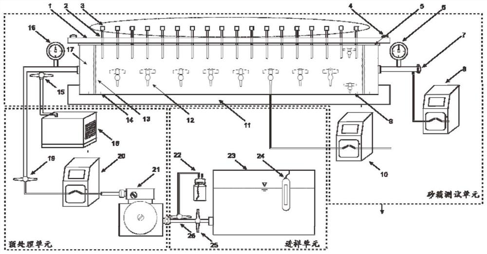
[0084] like figure 1 Shown: the large-scale experimental device for magnetic signal detection in solute migration under saturated medium of the present invention, the device includes: vacuum pump 18, water inlet valve 19, first port peristaltic pump 20, booster pump 21, sample bottle 22, water tank 23. Heating device 24, water tank valve 25, sample bottle valve 26;

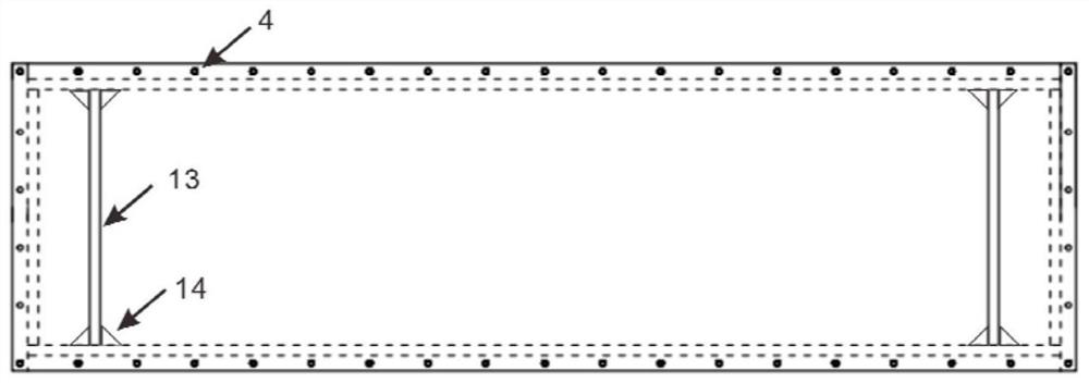
[0085] The sand box includes: sand box top plate 1, sand box top plate drilling 2, magnetic probe 3, top plate screw 4, rubber pad 5, water outlet pressure gauge 6, water valve and sampling point 7, second peristaltic pump 8, sand box Side wall vertical water valve and sampling point 9, side wall sampling point peristaltic pump 10, sand box bottom reinforcement device 11, sand box side wall horizontal water valve and sampling point 12, perforated partition and stainless steel mesh 13, perforated partition Plate reinforcement device 14, vacuum pump water valve 15, water inlet pressure gauge 16, compartment 17.

...

Embodiment 2

[0088] Embodiment 2, on the basis of Embodiment 1, turn on the switch of the heating device 24, maintain the water temperature at 25°C (above the indoor temperature), slowly inject the fluid, and turn on the booster pump 21 when the water tank pressure cannot guarantee the height of the water inlet head. The first peristaltic pump 20 slowly injects fluid (the flow rate should be lower than <20ml / s), and gradually removes the air inside the sand box. After the medium in the sand box is saturated, open the water outlet valve 7 of the sand box system and the second peristaltic pump 8, And adjust the peristaltic pump 8 and the peristaltic pump 20 to ensure a stable flow rate (the flow rate should be within the controllable range of the peristaltic pump).

Embodiment 3

[0089] Embodiment three, fill the sand layer inside the sand layer, and tighten the top plate screw 4, and the water inlet water valve 15 and the water outlet sampling place water valve 8, the water valve 12 and the water valve 9 at the sand box side wall sampling place, use Plug the plug to close the hole 2 on the top plate, turn on the vacuum pump 18, observe the change of the pressure gauge 16 at the water inlet, turn off the vacuum pump before reaching the maximum pressure bearing capacity of the sand box (≈ the maximum pressure measurement water head under saturated medium), turn on the sand box, and repeat the above steps After instructing the vacuum pump that the sand layer does not appear sunken, turn on the switch of the heating device 24, maintain the water temperature at 25°C (assumed value), slowly inject the fluid, and when the pressure of the water tank cannot guarantee the height of the water inlet head, turn on the booster pump 21, the first Peristaltic pump 20,...


PUM

PropertyMeasurementUnit
volumeaaaaaaaaaa

Abstract

The invention relates to the technical field of solute migration, in particular to a large-scale experimental device for detecting magnetic signals in the process of solute migration under a saturated medium. The device includes a sampling unit, a pretreatment unit and a sandbox testing unit, the sampling unit is connected to the sandbox testing unit through a pipeline, and the pretreatment unit is arranged on the connecting pipeline between the sampling unit and the sandbox testing unit. The device makes it suitable for magnetic signal inversion by adjusting the proportion of the sand box, and can add a fixed-source magnetic field when the magnetic signal is insufficient to generate an alternating electromagnetic field to enhance the magnetic signal. For collection, the bottom of the sand box and its surroundings are reinforced with wooden boards to avoid deformation and breakage of the joints of the sand box caused by excessive internal pressure of the sand box. The sand box is wrapped with heat-insulating materials to maintain temperature stability during the experiment. The whole set of experimental equipment does not contain any metal materials, so as to avoid interference to the magnetic signal monitoring.

Description

Technical field: [0001] The invention belongs to the technical field of solute migration, and in particular relates to a large-scale experimental device and method for detecting magnetic signals in the process of solute migration under a saturated medium. Background technique: [0002] The inversion of reservoir structure characteristics in deep saturated aquifers has always been the bottleneck of current exploration technology. The most important problem is that the currently applied tracer technology uses the inversion and analysis of water outlet concentration data, and cannot analyze The material signal is monitored in real time, and the results obtained by the tracer technology are two-dimensional, which cannot be used for three-dimensional tracer of the reservoir. In order to solve this problem, the research and development of new exploration technology has become an important research direction, among which magnetic detection technology is expected to solve this probl...

Claims


Application Information

Patent Timeline
Patent Type & Authority Patents(China)
IPC IPC(8): G01N27/72
CPCG01N27/72
Inventor 任亚倩宋伟孔彦龙程远志曹长乾
Owner INST OF GEOLOGY & GEOPHYSICS CHINESE ACAD OF SCI
Why Eureka
Try Eureka