
Remote control method and device for intelligent electric meter

A technology of remote control device and smart meter, which is applied in the direction of measurement device, measurement of electrical variables, electrical signal transmission system, etc., can solve the problem of external antenna damage, low efficiency of manual meter reading, and inability to read the meter when manual meter reading is small. Problems such as itemized data to achieve the effect of easy extraction and prevention of breakage

Inactive Publication Date: 2021-06-08
周建洪
View PDF10 Cites 0 Cited by
  • Summary
  • Abstract
  • Description
  • Claims
  • Application Information

AI Technical Summary

Problems solved by technology

[0003] At present, the smart meter uses the remote meter reading method for statistics. The remote meter reading system replaces the traditional manual meter reading method with a fully automatic meter reading method, which solves the low efficiency of manual meter reading and the inability to read out the inside of the meter. Problems with hourly segmented data
However, the current external antennas of smart meters are generally installed on the outside, lacking a protective structure that does not affect the received signal, making the external antenna vulnerable to external damage and reducing the accuracy of its remote meter reading control

Method used


Image

  • Remote control method and device for intelligent electric meter
  • Remote control method and device for intelligent electric meter
  • Remote control method and device for intelligent electric meter

Examples


Embodiment Construction

[0028] The following will clearly and completely describe the technical solutions in the embodiments of the present invention with reference to the accompanying drawings in the embodiments of the present invention. Obviously, the described embodiments are only some, not all, embodiments of the present invention. Based on the embodiments of the present invention, all other embodiments obtained by persons of ordinary skill in the art without making creative efforts belong to the protection scope of the present invention.

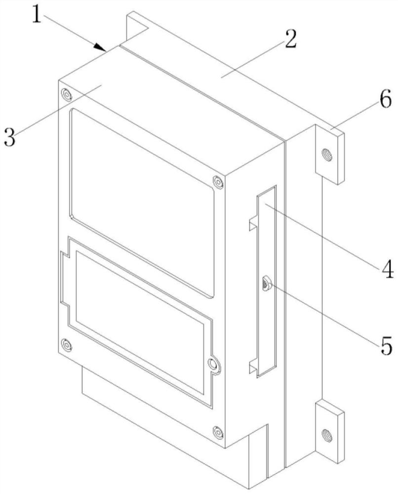
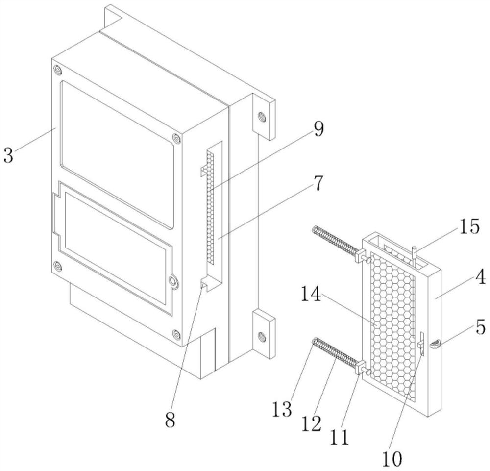
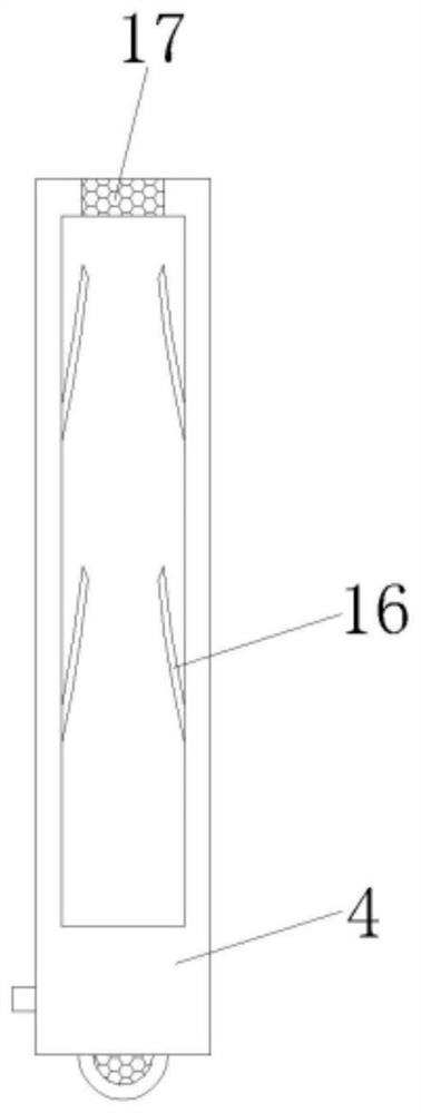
[0029] The present invention provides such Figure 1-7 The remote control device of a smart meter shown includes a smart meter collector 1, an external antenna box 4 plugged into the smart meter collector 1, an external antenna 15 installed inside the external antenna box 4, and a knob 5 , the smart meter collector 1 includes a first housing 2 and a second housing 3 fixedly connected to the first housing 2, a plug slot 7 is provided on the side of the second h...


PUM


Abstract

The invention discloses a remote control method and device for an intelligent electric meter. The remote control device comprises an intelligent electric meter collector, an external antenna box which is inserted in the intelligent electric meter collector, an external antenna which is disposed in the external antenna box, and a knob, wherein the intelligent electric meter collector comprises a first shell and a second shell which is fixedly connected with the first shell, an inserting groove is formed in the side face of the second shell, a rectangular groove is longitudinally formed in the side face of the external antenna box, the knob is inserted into the outer surface of the external antenna box, a clamping rod is welded to the end, extending into the rectangular groove, of the knob, and a clamping groove is formed in the side wall of an inner cavity of the rectangular groove. According to the remote control method and the device of the intelligent electric meter, normal signal receiving of the external antenna is not affected, a protection structure is provided, breaking is prevented, meanwhile, flowing of airflow is facilitated, ventilation and heat dissipation of the external antenna box and internal elements of the intelligent electric meter collector are achieved, and the remote control precision is improved.

Description

technical field [0001] The invention belongs to the technical field of smart meters, and in particular relates to a remote control method and device for a smart meter. Background technique [0002] The smart meter is the smart terminal of the smart grid. In addition to the basic power consumption measurement function of the traditional power meter, in order to adapt to the use of smart grid and new energy, it also has two-way multi-rate metering functions, user-side control functions, and various Intelligent functions such as two-way data communication function of data transmission mode, anti-stealing function, etc., smart meters represent the development direction of intelligent terminals for end-users of energy-saving smart grids in the future. [0003] At present, the smart meter uses the remote meter reading method for statistics. The remote meter reading system replaces the traditional manual meter reading method with a fully automatic meter reading method, which solves...

Claims


Application Information

Patent Timeline
IPC IPC(8): G08C19/00G08C17/02G01R11/00G01R11/04
CPCG08C19/00G08C17/02G01R11/00G01R11/04
Inventor 周建洪
Owner 周建洪
Learn More