A power cable laying device

A technology for laying devices and power cables, applied in cable laying equipment, transportation and packaging, thin material handling, etc., can solve the problems of labor-intensive and time-consuming, and achieve the effect of saving labor

Active Publication Date: 2022-07-19
广东欧姆龙电力工程有限公司 +1
View PDF0 Cites 3 Cited by
  • Summary
  • Abstract
  • Description
  • Claims
  • Application Information

AI Technical Summary

Problems solved by technology

[0004] The purpose of the present invention is to solve the shortcomings of the prior art that consume a lot of manpower and the operation process takes a lot of time, and propose a power cable laying device

Method used


Image

  • A power cable laying device
  • A power cable laying device
  • A power cable laying device

Examples


Embodiment Construction

[0025] The technical solutions in the embodiments of the present invention will be clearly and completely described below with reference to the accompanying drawings in the embodiments of the present invention. Obviously, the described embodiments are only a part of the embodiments of the present invention, but not all of the embodiments.

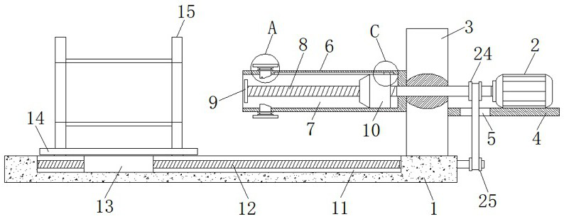
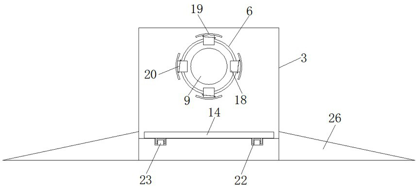
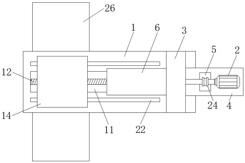
[0026] refer to Figure 1-6 , a power cable laying device, comprising a base 1 and a drive motor 2, a first support plate 3 is fixedly installed on the top of the base 1, a mounting plate 4 is fixedly installed on one end side wall of the first support plate 3, and the drive motor 2 is fixed Installed on the mounting plate 4, the mounting plate 4 is provided with a through opening 5, the other end side wall of the first support plate 3 is rotatably connected with a rotating shaft 6, and one end side wall of the rotating shaft 6 is provided with a notch 7, and the driving motor 2 The drive shaft is fixedly connected with a first threaded rod...


PUM


Abstract

The invention discloses a power cable laying device, comprising a base and a driving motor. A first support plate is fixedly installed on the top of the base, and a mounting plate is fixedly installed on one side wall of the first support plate. The motor is fixedly mounted on the mounting plate, and the mounting plate is provided with a through opening. The present invention uses the base, the drive motor, the first support plate, the installation plate, the through hole, the rotating shaft, the notch, the first threaded rod, the push block, the sliding groove, the second threaded rod, the sliding block and the supporting mechanism. , the cable take-up wheel is moved to the rotating shaft by pushing the cable take-up wheel to the bearing plate, and then the first threaded rod and the second threaded rod are driven to rotate by the driving motor, and the multiple support blocks are pushed through the push block at the same time. The block movement can realize the purpose of supporting the cable take-up wheel through the plurality of second support plates, so that the erection purpose of the cable take-up wheel can be realized, and a lot of manpower can be saved.

Description

technical field [0001] The invention belongs to the technical field of cable laying, and in particular relates to a power cable laying device. Background technique [0002] The cable is usually a rope-like cable formed by twisting several or several groups of conductors. Each group of conductors is insulated from each other and often twisted around a center. In the process of electric power construction, it is often necessary to lay cables. Power cables are used for urban underground power grids and internal power supply in industrial and mining enterprises. [0003] In the process of laying the cable, the cable winding wheel is usually suspended and erected, and then the cable is pulled to make the cable take out from the winding rack to achieve the purpose of laying the cable, but the existing cable winding wheel is erected on the winding rack. It is generally operated manually. The staff lifts the reel and then erects it on the reel stand. This method is troublesome and ...

Claims


Application Information

Patent Timeline
Patent Type & Authority Patents(China)
IPC IPC(8): H02G1/06B65H49/36
CPCH02G1/06B65H49/36
Inventor 高伟
Owner 广东欧姆龙电力工程有限公司
Why Eureka
Try Eureka