A rotor punch, rotor, permanent magnet synchronous motor and vehicle

A rotor punching and punching technology, which is applied in the field of rotors, permanent magnet synchronous motors and vehicles, and rotor punching, can solve the problem that the structural strength of the motor cannot meet the requirements of use, the output torque of the motor is limited, and it cannot provide sufficient magnetic flux area and other issues, to achieve the effect of improving acceleration performance and driving mileage, improving performance, and improving driving comfort

Active Publication Date: 2022-05-03
深蓝汽车科技有限公司
View PDF11 Cites 1 Cited by
  • Summary
  • Abstract
  • Description
  • Claims
  • Application Information

AI Technical Summary

Problems solved by technology

If the output torque of the drive motor is small, it will affect the acceleration performance of the vehicle; if the efficiency of the drive motor is low, it will seriously affect the mileage of the vehicle, affect the ride experience of passengers, and even cause complaints from customers
Most of the existing technical solutions adopt the following rotor structure types: "one" type magnetic pole structure, the motor rotor structure strength is high, but the output torque is not enough; the "V" type structure provides a larger magnetic flux area, but the distance from the outer circle of the rotor Farther away, the reluctance of the magnetic circuit flow is increased, and the output torque of the motor is limited; the "V" + "one" type can get a larger magnetic flux area, but if the outer "one" permanent magnet is too long, the motor The structural strength cannot meet the requirements of use, and the permanent magnet is too short to provide sufficient magnetic flux area, so the output torque increase of the motor is still limited

Method used


Image

  • A rotor punch, rotor, permanent magnet synchronous motor and vehicle
  • A rotor punch, rotor, permanent magnet synchronous motor and vehicle
  • A rotor punch, rotor, permanent magnet synchronous motor and vehicle

Examples


Embodiment Construction

[0024] The specific embodiments of the present invention will be further described below in conjunction with the accompanying drawings.

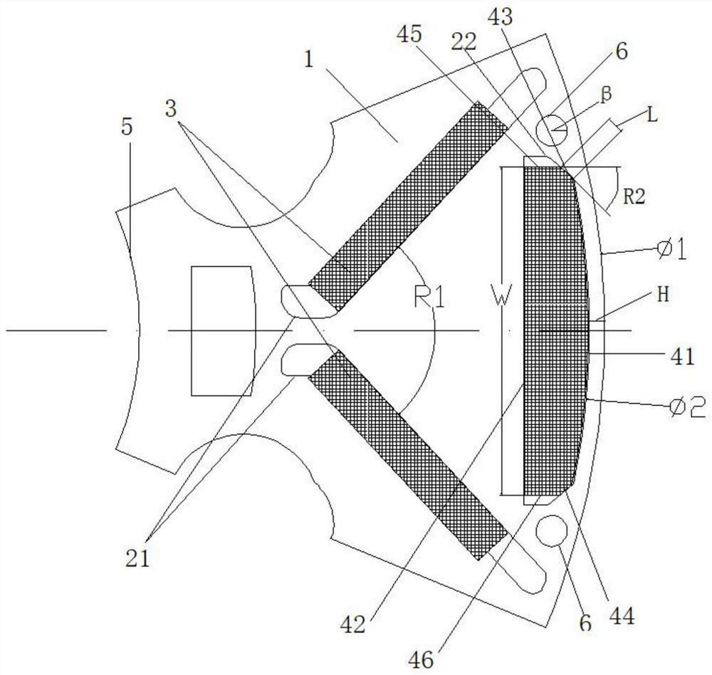
[0025] see figure 1 As shown, this embodiment discloses a rotor stamping, including a stamping body 1, the stamping body 1 is provided with an axial hole 5 and a plurality of permanent magnet pole slots uniformly arranged on the outside of the axial hole 5 in the circumferential direction group, the permanent magnet pole slot group includes two first permanent magnet slots 21 and a second permanent magnet slot 22, the two first permanent magnet slots 21 are arranged in a "eight" shape with a large opening facing outward, the first Two permanent magnet grooves 22 are arranged at the big opening of "eight" shape, and first permanent magnet 3 is all arranged in each first permanent magnet groove 21, and second permanent magnet 3 is all arranged in each second permanent magnet groove 22. magnet4;

[0026] The outer surface of the second perma...


PUM


Abstract

The invention discloses a rotor punching sheet, which includes a punching sheet body, the punching sheet body is provided with an axial hole and a plurality of permanent magnetic pole slot groups uniformly arranged outside the axial hole in the circumferential direction, and the permanent magnetic pole slot group includes Two first permanent magnet slots and one second permanent magnet slot, the two first permanent magnet slots are arranged in a "eight" shape with a large opening facing outward, and the second permanent magnet slot is arranged in the "eight" shape At the large opening, a first permanent magnet is arranged in each first permanent magnet slot, and a second permanent magnet is arranged in each second permanent magnet slot; the outer surface of the second permanent magnet is a first arc surface , the second permanent magnet slot is correspondingly provided with an arcuate surface matching the first arcuate surface. Through the rotor stamping of the present invention, the magnetic flux area of ​​the entire permanent magnet is increased, the magnetic flux path from the second permanent magnet to the outer circle of the rotor is reduced, the magnetic resistance is reduced, and the output torque is improved.

Description

technical field [0001] The invention relates to the technical field of motors, in particular to a rotor punch, a rotor, a permanent magnet synchronous motor and a vehicle. Background technique [0002] The drive motor system is the core of new energy vehicles, and the performance characteristics of the drive motor determine the driver's driving comfort experience. Performance optimization of the drive motor is therefore an integral part of the powertrain design of modern electric vehicles. If the output torque of the driving motor is small, it will affect the acceleration performance of the vehicle; if the efficiency of the driving motor is low, it will seriously affect the mileage of the vehicle, affect the ride experience of passengers, and even cause complaints from customers. Most of the existing technical solutions adopt the following rotor structure types: "one" type magnetic pole structure, the motor rotor structure strength is high, but the output torque is not enou...

Claims


Application Information

Patent Timeline
Patent Type & Authority Patents(China)
IPC IPC(8): H02K1/276H02K21/14
CPCH02K1/276H02K21/14H02K2213/03
Inventor 米泽银卢有君杜长虹周安健苏志鹏
Owner 深蓝汽车科技有限公司
Why Eureka
Try Eureka