A kind of micro swing motor and its preparation method

A swing motor, miniature technology, applied in the direction of electric components, electric vehicles, manufacturing motor generators, etc., can solve the problems of difficult assembly, poor reliability of circuit connection, difficult disassembly and maintenance, etc., to achieve easy assembly and simplified structure The effect of designing and simplifying the structure

Active Publication Date: 2022-05-27
ZHONGSHAN GCHIMAY ELECTRIC APPLIANCE
View PDF6 Cites 0 Cited by
  • Summary
  • Abstract
  • Description
  • Claims
  • Application Information

AI Technical Summary

Problems solved by technology

Although this technical solution can solve the problem that the output shaft of the traditional iron-core DC vibrating motor cannot provide reciprocating swing, the miniature reciprocating swing has the disadvantages of complex structure, many assembly processes and assembly problems due to the large number of parts used. Difficult to accurately place, high manufacturing costs and other issues
In particular, the winding of the rotor needs to be wound in the slot of the iron core, and the connection between the rotor winding coil and the external power supply needs to be connected through the conductive sheet for reversing action and the brush for maintaining sliding connection, resulting in a large overall diameter and reliable circuit connection Poor performance and short service life; and once a small number of parts are damaged, it is difficult to disassemble and repair, and can only be scrapped as a whole
[0004] In summary, with the development of personal care consumer electric products such as electric toothbrushes, it is proposed to reduce the number of parts, reduce the overall diameter, improve the reliability of circuit connection, easy to manufacture, long service life and comprehensive low cost for micro motor products. needs that cannot be met by existing technologies
In addition, in order to meet the needs of individualization and small batches of electric products, technical requirements such as the output torque, swing amplitude, swing frequency and other operating parameters of motor products can be flexibly adjusted, and the existing technology cannot meet these requirements.

Method used


Image

  • A kind of micro swing motor and its preparation method
  • A kind of micro swing motor and its preparation method
  • A kind of micro swing motor and its preparation method

Examples


Embodiment 1

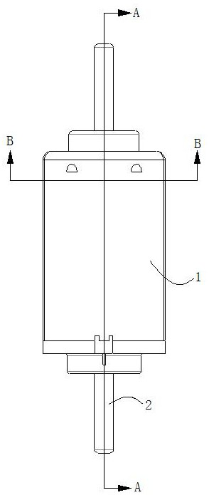
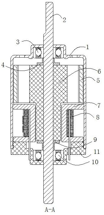
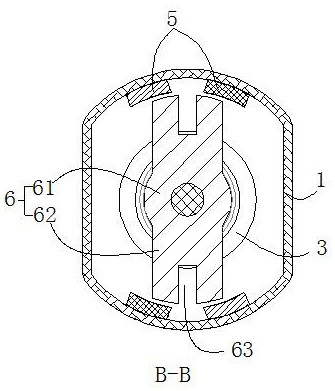
[0042] See Figure 1-Figure 6 , the micro-swing motor provided by the embodiment of the present invention includes a stator part and a rotor part, and the stator part is composed of a casing 1, two pairs of permanent magnets 5 and a rear end cover 11 respectively arranged on the casing 1, wherein The two pairs of permanent magnets 5 are arranged on the inner side of the casing 1 at intervals in the axial direction; 8. It is composed of a coil bobbin 7, wherein the magnetic conductive magnetic core 6 is a magnetic conductive magnetic core with a "T" shape in axial section, and the head of the magnetic conductive magnetic core 6 is a rectangle whose length direction is perpendicular to the rotating shaft 2 The magnetic core head 61, the tail part of the magnetic core 6 is the magnetic core column part 61 whose length direction is parallel to the rotating shaft 2, and the magnetic core head 61 and the magnetic core column part 61 are integrated, and its axial position is provided...

Embodiment 2

[0076] see Figure 7-Figure 12 , the micro-swing motor and the preparation method thereof provided in this embodiment are basically the same as those in Embodiment 1, except that:

[0077] Specifically, protruding portions 64 for increasing the magnetic flux rate of the magnetic core head 62 are further provided on both sides of the magnetic core head portion 62 in the circumferential direction along the width direction of the magnetic core head portion 62 .

[0078] In this embodiment, the protruding part 64 and the magnetic core head 62 are integrally formed, and the cross section of the protruding part 64 is rectangular; under the condition that the lateral length of the magnetic core head 62 remains unchanged, the The protrusions arranged along the width direction on both sides of the circumferential direction can effectively increase the overall magnetic flux area of ​​the magnetic core head, improve the magnetic flux rate of the magnetically conductive magnetic core, and...


PUM


Abstract

The invention discloses a miniature swing motor and a preparation method thereof. The motor includes a stator part and a rotor part. The stator part is composed of a casing, two pairs of permanent magnets and a rear end cover; the rotor part is composed of a rotating shaft, a magnetically permeable magnetic core, an electromagnetic Composed of coils and coil bobbins, the magnetically conductive magnetic core is in the shape of a "T". The coil bobbin and the electromagnetic coil are set on the core column and then placed on the inner side of the casing. The electromagnetic coil does not follow the magnetic conduction when the motor is working. The magnetic core rotates; when the forward and reverse alternating current is passed into the electromagnetic coil, the alternating magnetic field generated by it interacts with the fixed magnetic field of the permanent magnet to make the rotating shaft reciprocate within the range of rotation angle relative to the stator. The present invention greatly reduces product cost and improves product performance by synchronously simplifying the structure and preparation steps of the product. The output torque, rotation angle range and frequency can be flexibly adjusted to achieve a smaller diameter and output more suitable torque, rotation angle and frequency. And easy to manufacture.

Description

technical field [0001] The invention relates to the technical field of micro-motor manufacturing, in particular to a micro-oscillating motor and a preparation method thereof. Background technique [0002] Traditional iron-core DC vibration micromotors are widely used in vibration products such as electric toothbrushes, health care equipment, and personal care. However, the traditional iron core DC vibration motor is to install an eccentric block on the output shaft of the iron core motor, and the rotation of the motor drives the eccentric block to rotate to generate centrifugal force to achieve vibration. In this vibration mode, due to the existence of unbalanced centrifugal force, the output shaft will continuously generate radial pressure on the bearing, which makes the bearing easy to wear, thus reducing the service life and reliability of the product. In addition, the output shaft of the traditional iron-core DC vibration motor cannot provide reciprocating oscillation. ...

Claims


Application Information

Patent Timeline
Patent Type & Authority Patents(China)
IPC IPC(8): H02K33/16H02K1/278H02K3/52H02K15/00H02K15/03H02K33/18
CPCH02K33/16H02K33/18H02K15/00H02K15/03H02K3/522H02K1/278Y02T10/64
Inventor 钱志存吴永红
Owner ZHONGSHAN GCHIMAY ELECTRIC APPLIANCE
Why Eureka
Try Eureka