Stator of outer rotor motor and assembly method

An external rotor motor and stator technology, applied in electromechanical devices, manufacture of stator/rotor body, electrical components, etc., can solve the difficulty in embedding wires of concentrated winding forming coils, easy damage to insulating materials and winding coils, direct winding or embedding of windings Solve problems such as difficult wires, achieve the effects of easy wire embedding, improved air-gap magnetic density waveform, and improved slot fullness

Inactive Publication Date: 2020-08-28
JIANGSU JIAXUAN INTELLIGENT IND TECH CO LTD
View PDF5 Cites 0 Cited by
  • Summary
  • Abstract
  • Description
  • Claims
  • Application Information

AI Technical Summary

Problems solved by technology

[0002] In the external rotor motors of the prior art, the structure of the stator core is usually an integrated structure of the tooth yoke. Due to the limitation of the opening of the upper slot of the integrated stator, it is difficult to directly wind the winding or insert the wire, and the slot fill rate is low. high manufacturing cost
At the same time, the one-piece structure of the tooth yoke will lead to difficulties in inserting wires when using concentrated winding forming coils, and problems such as easy damage to insulating materials and winding coils
In the prior art, the formed coil has an inverted trapezoidal structure, with upper width and lower bottom narrow, and the teeth of the integrated stator core are also wider and narrower at the bottom. The process of inserting wires needs to first expand the lower side of the formed coil to make it wider than the teeth of the iron core. The width of the upper side, and then nest it on the upper side of the tooth, then loosen the lower side of the forming coil, and press it down until it is completely nested on the entire tooth. In the process of expanding the forming coil and nesting on the tooth, it is easy to damage Coil Insulation Material
In addition, open slots are usually used during installation, which deteriorates the air-gap magnetic density waveform, resulting in greater eddy current loss of the magnetic steel

Method used


Image

  • Stator of outer rotor motor and assembly method
  • Stator of outer rotor motor and assembly method
  • Stator of outer rotor motor and assembly method

Examples


Embodiment 1

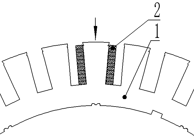
[0038] Embodiment 1 provides a stator with pole shoes.

[0039] The stator includes a stator core and a winding coil 2. The stator core is disassembled into a stator yoke 4 and a plurality of stator teeth 3. The plurality of stator teeth 3 are evenly distributed on the outer periphery of the stator yoke 4 in the circumferential direction. All the stator teeth 3 and the stator yoke 4 They are detachably connected together by a splicing structure, and are fixed to each other by pins 5. The stator yoke 4 is an integrated full circle structure. A plurality of stator teeth and the stator yoke 4 form a stator punch, and the stator punches are stacked in multiple layers. Pressed to form the stator core. details as follows:

[0040] A stator of an external rotor motor, a stator core and a winding coil 2, wherein the stator core includes stator teeth 3, a stator yoke 4, and pins 5, and a plurality of stator teeth 3 are evenly distributed on the outer periphery of the stator yoke 4 in ...

Embodiment 2

[0046] Embodiment 2 provides a stator with a cooling medium pipeline.

[0047] The stator includes a stator core and a winding coil 2. The stator core is disassembled into a stator yoke 4 and a plurality of stator teeth 3. The plurality of stator teeth 3 are evenly distributed on the outer periphery of the stator yoke 4 in the circumferential direction. All the stator teeth 3 and the stator yoke 4 They are all detachably connected together by a splicing structure, and are fixed to each other by pin 5, as follows:

[0048] A stator of an external rotor motor, including a stator core and a winding coil 2, wherein the stator core includes stator teeth 3, a stator yoke 4, and pins 5, and a plurality of stator teeth 3 are evenly distributed on the outer periphery of the stator yoke 4 in the circumferential direction, and the stator teeth 3 is detachably connected with the stator yoke 4, the winding coil 2 is wound on the stator yoke 3; a plurality of positioning slots 42 are opened...

Embodiment 3

[0055] Embodiment 3 provides a stator assembly method of an outer rotor motor.

[0056] The method comprises the steps of:

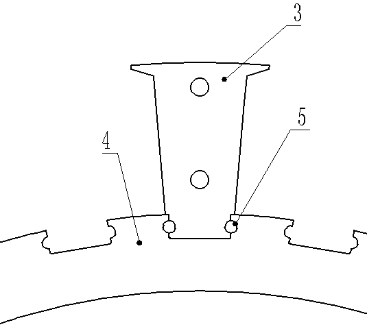
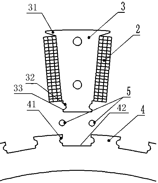
[0057] S1: the first fixing groove 32 is opened on both sides of the fixing head 33 at the bottom of the stator tooth 3;

[0058] S2: The stator yoke 4 is provided with a plurality of positioning slots 42, and the two inner sides opposite to the positioning slots 42 are provided with second fixing slots 41;

[0059] S3: The winding coil 2 is wound on the stator tooth 3 to form a whole;

[0060] S4: Insert the integral fixing head 33 into the positioning groove 42 along the radial direction of the stator yoke 4 so that the first fixing groove 32 and the second fixing groove 41 cooperate to form a cylindrical groove;

[0061] S5: Insert the cylindrical pin 5 into the groove along the axial direction of the stator yoke 4 for fixing;

[0062] Wherein the top of the stator tooth 3 is provided with a pole shoe 31 .

[0063] In a preferred embodiment, the s...


PUM


Abstract

The invention relates to the field of external rotor motors, and provides a stator of an external rotor motor and an assembly method, the stator comprises a stator core, the stator core comprises stator teeth (3), one end of each stator tooth is provided with a fixing head (33), and the outer side surface of each fixing head (33) is provided with a first fixing groove (32); the stator yoke (4) isprovided with a plurality of positioning grooves (42), and the inner side surfaces of the positioning grooves (42) are provided with second fixing grooves (41); wherein the plurality of stator teeth (3) are uniformly distributed at the periphery of the stator yoke (4) in the circumferential direction, the fixing head (33) is matched with a positioning groove (42) in the stator yoke (4), and the stator teeth (3) are detachably connected with the stator yoke (4); the pin (5) is matched with the first fixing groove (32) and the second fixing groove (41); and the winding coil (2) is wound on the stator teeth (3) of the stator core. The winding coil disclosed by the invention is easy to embed, does not damage an insulating material, and effectively improves the slot fullness rate.

Description

technical field [0001] The invention relates to the field of external rotor motors, in particular to a stator and an assembly method of an external rotor motor. Background technique [0002] In the external rotor motors of the prior art, the structure of the stator core is usually an integrated structure of the tooth yoke. Due to the limitation of the opening of the upper slot of the integrated stator, it is difficult to directly wind the winding or insert the wire, and the slot fill rate is low. Manufacturing costs are high. At the same time, the one-piece structure of the tooth yoke will lead to difficulties in inserting wires when using concentrated winding forming coils, and problems such as easy damage to insulating materials and winding coils. In the prior art, the formed coil has an inverted trapezoidal structure, with upper width and lower bottom narrow, and the teeth of the integrated stator core are also wider and narrower at the bottom. The process of inserting w...

Claims


Application Information

Patent Timeline
Patent Type & Authority Applications(China)
IPC IPC(8): H02K1/14H02K3/28H02K1/20H02K15/02
CPCH02K1/146H02K1/20H02K3/28H02K15/02
Inventor 张春晖左成
Owner JIANGSU JIAXUAN INTELLIGENT IND TECH CO LTD
Why Eureka
Try Eureka