
An image acquisition device for on-site monitoring of a meeting and its use method

An image acquisition device and on-site monitoring technology, applied in image communication, instruments, televisions, etc., can solve problems affecting image acquisition clarity, installation position orientation angle adjustment, and impact on meeting progress, so as to improve maintenance or replacement efficiency and quickly Simple and convenient installation and disassembly

Active Publication Date: 2022-04-08
辰卓科技有限公司
View PDF11 Cites 0 Cited by
  • Summary
  • Abstract
  • Description
  • Claims
  • Application Information

AI Technical Summary

Problems solved by technology

[0003] However, most of the existing image acquisition devices for on-site monitoring of the meeting are only a single fixed camera, and its installation position and orientation angle cannot be adjusted, resulting in a certain dead angle of image acquisition at the meeting site, making the image acquisition content incomplete and affecting To record the important content of the meeting, at the same time, most of the cameras of the existing image acquisition devices for on-site monitoring of the meeting are directly exposed on the top of the meeting room, and when the meeting is not in progress, it is also exposed outside, which makes the surface of the lens easy to Contaminated with dust, which in turn affects the clarity of image acquisition. In addition, most of the cameras of the existing image acquisition devices for on-site conference monitoring are directly installed and fixed by screws. When they are damaged and need to be repaired or replaced, many more Only by turning the screw once can it be disassembled and installed, resulting in a reduction in the efficiency of maintenance or replacement, which seriously affects the progress of the meeting and is not conducive to actual use.

Method used


Image

  • An image acquisition device for on-site monitoring of a meeting and its use method
  • An image acquisition device for on-site monitoring of a meeting and its use method
  • An image acquisition device for on-site monitoring of a meeting and its use method

Examples


Embodiment

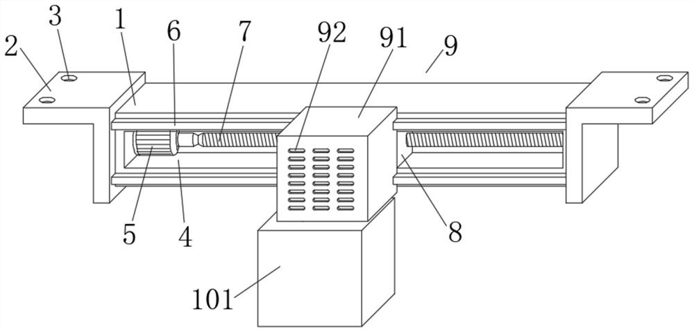
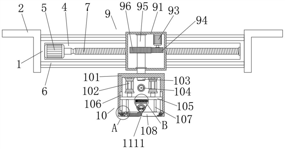
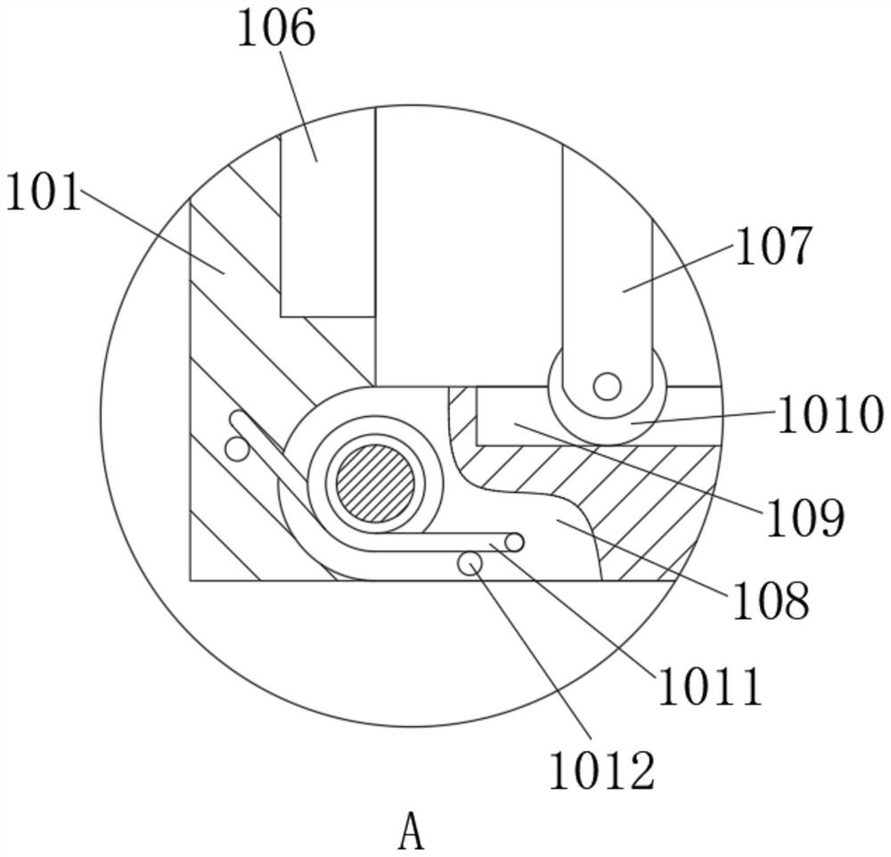
[0029]An image acquisition device for on-site monitoring of a meeting, comprising an installation box 1, the two ends of the installation box 1 are fixedly connected with a fixed plate 2 with an L-shaped structure, and the top of the fixed plate 2 is provided with two fixed holes 3 , by setting the fixing plate 2 and the fixing hole 3, it is convenient to install and fix the whole device better; the outside of the installation box 1 is provided with a transmission groove 4, and one side of the inner wall of the transmission groove 4 is fixedly installed with the first servo Motor 5, the output shaft of the first servo motor 5 is fixedly connected with a screw mandrel 7 through a coupling, and the end of the screw mandrel 7 away from the first servo motor 5 is rotationally connected with the inner wall of the transmission groove 4, and the screw mandrel The outer thread of 7 is connected with slider 8, and the outer side of described slider 8 is slidably connected with the inner...


PUM


Abstract

The invention discloses an image acquisition device for on-site monitoring of a meeting and a method for using the same. a fixing hole, and a transmission groove is opened on the outside of the installation box. The present invention is compact in structure, simple and convenient in operation, and strong in practicability. By arranging screw drive and rotating mechanism, the installation position and orientation angle of the camera can be adjusted, thereby avoiding There is a dead angle of image collection, which affects the monitoring effect of the meeting. At the same time, by setting the telescopic adjustment mechanism, the camera can be shrunk and protected when the meeting is not in progress, so as to avoid affecting the clarity of image collection due to dust on the surface of the camera lens. In addition, by setting The installation mechanism can quickly install and disassemble the camera, thereby greatly improving the maintenance or replacement efficiency of the camera, which is beneficial to actual use.

Description

technical field [0001] The invention belongs to the field of image acquisition, in particular to an image acquisition device for on-site monitoring of a meeting and a method for using the same. Background technique [0002] In existing life, a meeting refers to an organized, leading, and purposeful discussion activity. It is carried out in a limited time and place according to certain procedures. To record, an image acquisition device is often used to monitor it at the meeting site, so as to facilitate the recording of important content of the meeting. However, in the existing technology, a camera is often used as the image acquisition device for the meeting site. [0003] However, most of the existing image acquisition devices for on-site monitoring of the meeting are only a single fixed camera, and its installation position and orientation angle cannot be adjusted, resulting in a certain dead angle of image acquisition at the meeting site, making the image acquisition cont...

Claims


Application Information

Patent Timeline
Patent Type & Authority Patents(China)
IPC IPC(8): H04N7/18H04N5/232H04N5/225F16M11/04F16M11/08F16M11/18G08C17/02
CPCH04N7/185F16M11/045F16M11/18F16M11/08G08C17/02H04N23/51H04N23/66H04N23/50
Inventor 孙青龙
Owner 辰卓科技有限公司
Learn More