Friction stir welding device for welding storage tank of aerospace vehicle

A friction stir welding and carrier technology, which is applied in welding equipment, non-electric welding equipment, metal processing equipment, etc., can solve the problems of poor synchronization, damage to product welding quality, and easy damage to equipment, so as to improve and solve synchronization problems. The effect of reduced precision

Active Publication Date: 2021-06-11
BEIJING LANDSPACETECH CO LTD
View PDF11 Cites 3 Cited by
  • Summary
  • Abstract
  • Description
  • Claims
  • Application Information

AI Technical Summary

Problems solved by technology

The inventor found during the research process that this type of equipment is still suitable for welding small-sized products or storage tanks, but for super-long and super-large-sized storage tanks, the moment of inertia caused by the large self-weight rotation will destroy the synchronization between mechanisms. After long-term use, the synchronization becomes poor and the welding quality cannot be guaranteed, and there are defects such as easy damage to the equipment, error reporting and difficult maintenance operations.
[0004] In view of this, it is urgent to design a friction stir welding device for the welding of space vehicle storage tanks to solve the damage to the welding quality of products caused by the moment of inertia caused by the rotation of the storage tank's own weight, and to improve the welding quality of large-size storage tanks

Method used


Image

  • Friction stir welding device for welding storage tank of aerospace vehicle
  • Friction stir welding device for welding storage tank of aerospace vehicle
  • Friction stir welding device for welding storage tank of aerospace vehicle

Examples


Embodiment Construction

[0027] The characteristics and exemplary embodiments of various aspects of the present invention will be described in detail below. In order to make the purpose, technical solutions and advantages of the present invention clearer, the present invention will be further described in detail below in conjunction with the accompanying drawings and specific embodiments. It should be understood that the specific embodiments described here are only configured to explain the present invention and to exemplify the principle of the present invention, and are not configured to limit the present invention. Additionally, the mechanical components in the figures are not necessarily drawn to scale. For example, the size of some structural components or regions in the drawings may be exaggerated for other structural components or regions, so as to facilitate the understanding of the embodiments of the present invention.

[0028] The orientation words appearing in the following description are ...


PUM


Abstract

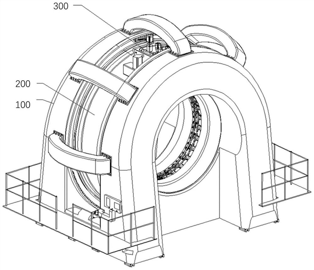
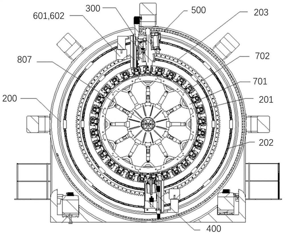
The invention provides a friction stir welding device for welding a storage tank of an aerospace vehicle. The friction stir welding device comprises a frame in a hollow portal frame form and used for fixedly arranging a to-be-welded storage tank, an annular sliding plate and a friction stir welding machine head. The annular sliding plate is a hollow circular sliding plate and is internally provided with a first annular guide rail, a second annular guide rail and an annular gear ring. The friction stir welding machine head is installed on the annular sliding plate and erected on the first annular guide rail and the second annular guide rail, and the friction stir welding machine head is driven on the annular gear ring to run around the first annular guide rail and the second annular guide rail so as to complete circumferential welding of the storage box to be welded. According to the device, the problem that the precision is reduced after the device is used for a long time due to large inertia caused by synchronous rotation is solved, and the practicability of the device is also improved.

Description

technical field [0001] The invention relates to the field of friction stir welding, in particular to a friction stir welding device used for welding storage tanks of aerospace vehicles. Background technique [0002] Friction stir welding technology has been hailed as the most creative invention in the past 30 years in the field of welding. It is a high-quality, efficient, green, low-cost, and low-distortion solid-phase welding method that completely solves the problems caused by welding of various non-ferrous metals. A series of problems in the future, and gradually replace the fusion welding method, has been widely used in aviation and aerospace fields. [0003] At present, domestic conventional storage tank friction stir welding equipment adopts the form that the friction stir welding head is fixed, and the storage tank to be welded moves and rotates. The inventor found during the research process that this type of equipment is still suitable for welding small-sized produ...

Claims


Application Information

Patent Timeline
Patent Type & Authority Applications(China)
IPC IPC(8): B23K20/12B23K20/26B23P23/04
CPCB23K20/12B23K20/26B23P23/04
Inventor 季卫卫苏志强于乐庆宋晓伟
Owner BEIJING LANDSPACETECH CO LTD
Why Eureka
Try Eureka