Automatic line-edge loading rack

A technology of automatic feeding and material racking, applied in the field of material racking, can solve the problems of occupying many working hours, tight station line space, inconvenient operation, etc., to save time, improve use efficiency, and ensure stability.

Inactive Publication Date: 2021-06-11
DESIGN INST NO 9 MINISTRY OF MECHINE BUILDING
View PDF5 Cites 0 Cited by
  • Summary
  • Abstract
  • Description
  • Claims
  • Application Information

AI Technical Summary

Problems solved by technology

[0002] In the automobile assembly line, most of the materials are stored on the material racks on the production line side, and the space on the line side of some stations is tight, and only one material rack can be placed. In order not to affect the production line, the material racks are designed to be rotatable In this way, one batch of delivery can be stored on the side of the retrieving port and the side of the loading port of the material rack (each delivery batch sends 12 material boxes), and the assembly worker takes all the material boxes at the retrieving port. Finally, the assembler rotates the material rack 180 degrees, the assembler can continue to take the material boxes in order, and the distribution personnel manually put the next batch of material boxes into the material loading port of the material rack, and return after the loading is completed. The feeding method is inconvenient to operate and takes up a lot of man-hours, so we designed an automatic feeding rack device

Method used


Image

  • Automatic line-edge loading rack
  • Automatic line-edge loading rack
  • Automatic line-edge loading rack

Examples


Embodiment Construction

[0025] The following will clearly and completely describe the technical solutions in the embodiments of the present invention with reference to the accompanying drawings in the embodiments of the present invention. Obviously, the described embodiments are only some, not all, embodiments of the present invention. Based on the embodiments of the present invention, all other embodiments obtained by persons of ordinary skill in the art without making creative efforts belong to the protection scope of the present invention.

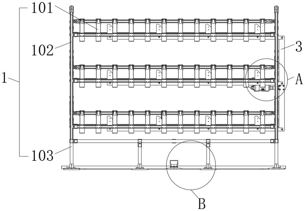
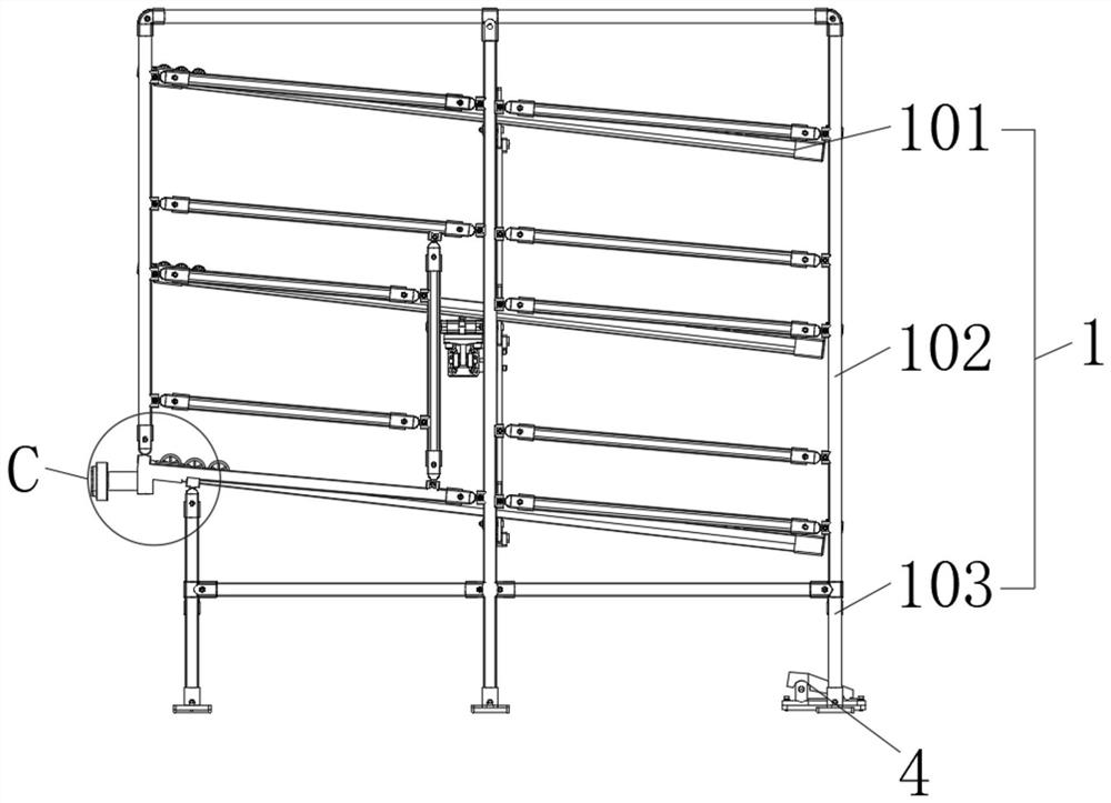
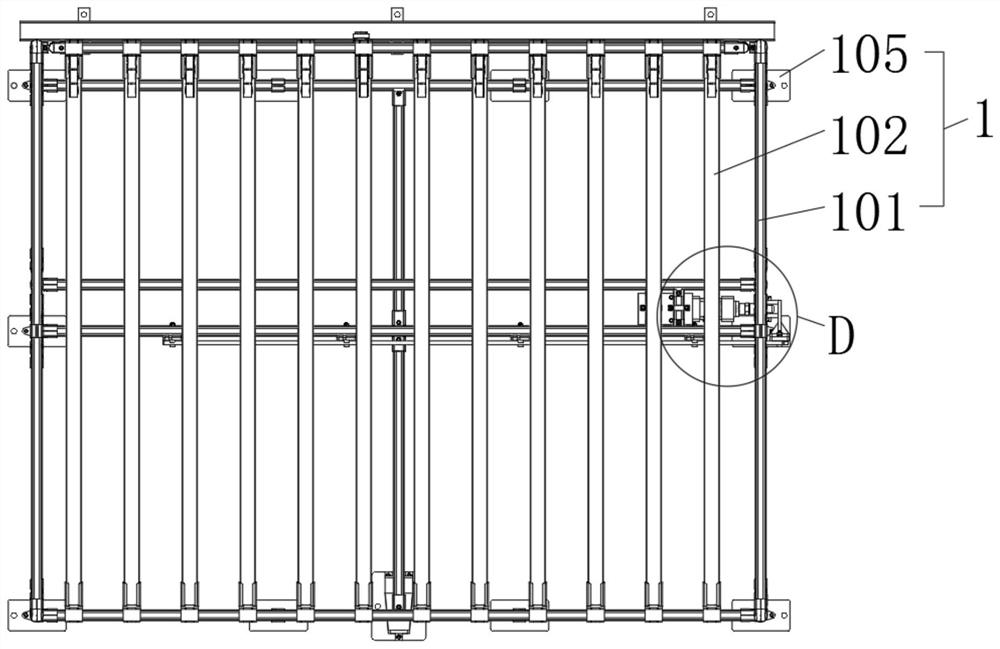
[0026] see Figure 1-8 , the present invention provides a technical solution: a line edge automatic feeding rack, including: a fluent shelf 1, a lever 2, a blocking mechanism 3 and a foot switch 4, the fluent shelf 1 is a three-layer inclined fluent shelf, The material box can be transported and loaded through the inclination of the fluent shelf 1. The blocking mechanism 3 is installed on the fluent shelf 1, and the blocking mechanism 3 is specifically install...


PUM


Abstract

The invention discloses an automatic line-edge loading rack. The automatic line-edge loading rack comprises a rolling goods shelf, a shifting rod, a blocking mechanism and a foot switch, wherein the rolling goods shelf is a three-layer inclined rolling goods shelf, the blocking mechanism is installed on the rolling goods shelf and electrically connected with the foot switch, and a fixing plate is fixedly installed at the lower end of the foot switch; an installation plate is fixedly installed on the ground at the front side of the rolling goods shelf, the shifting rod is installed at the lower end of the rear side of the rolling goods shelf, the foot switch is manually treaded with feet, the foot switch directly controls the blocking mechanism to fall down, the blocking effect on a material box is eliminated, at the moment, the material box slides to a material taking port in the front side of the material frame from the rear side of the material frame, simple operation, convenient use, and humanized and reasonable design are achieved, a large amount of labor force is saved, and the working efficiency is increased; and moreover, the device is simple in structure, convenient to machine and maintain, and free of harsh requirements for the manufacturing level, installation precision, operation conditions, lubrication and the like of parts.

Description

technical field [0001] The invention relates to the technical field of racks, and the specific field is an automatic feeding rack at the edge of a line. Background technique [0002] In the automobile assembly line, most of the materials are stored on the material racks on the production line side, and the space on the line side of some stations is tight, and only one material rack can be placed. In order not to affect the production line, the material racks are designed to be rotatable In this way, one batch of delivery can be stored on the side of the retrieving port and the side of the loading port of the material rack (each delivery batch sends 12 material boxes), and the assembly worker takes all the material boxes at the retrieving port. Finally, the assembler rotates the material rack 180 degrees, the assembler can continue to take the material boxes in order, and the distribution personnel manually put the next batch of material boxes into the material loading port o...

Claims


Application Information

Patent Timeline
Patent Type & Authority Applications(China)
IPC IPC(8): B65G47/74B65G47/88
CPCB65G47/74B65G47/8823
Inventor 延玉军
Owner DESIGN INST NO 9 MINISTRY OF MECHINE BUILDING
Why Eureka
Try Eureka