Low-pollution combustion chamber provided with premixing and pre-evaporating ring pipe

A combustion chamber and pre-evaporation technology, applied in combustion chambers, continuous combustion chambers, combustion methods, etc., can solve the problems of inability to meet the low pollution requirements of the engine, high CO and UHC emissions, and uneven local equivalence ratios, and achieve a simple structure. , The outlet mixture is uniform and easy to process.

Active Publication Date: 2010-07-28
BEIHANG UNIV
View PDF11 Cites 64 Cited by
  • Summary
  • Abstract
  • Description
  • Claims
  • Application Information

AI Technical Summary

Problems solved by technology

In the low power state, the equivalent ratio of the combustion zone is very low, which is far lower than the above-mentioned equivalence ratio range required for low-pollution combustion. At this time, although NOx emissions are low, CO and UHC emissions are high
In addition, because the conventional combustion chamber generally adopts the diffusion combustion method, the local equivalence ratio is not uniform, so for the conventional combustion chamber, it cannot meet the low pollution requirements in the entire engine operating range

Method used


Image

  • Low-pollution combustion chamber provided with premixing and pre-evaporating ring pipe
  • Low-pollution combustion chamber provided with premixing and pre-evaporating ring pipe
  • Low-pollution combustion chamber provided with premixing and pre-evaporating ring pipe

Examples


Embodiment Construction

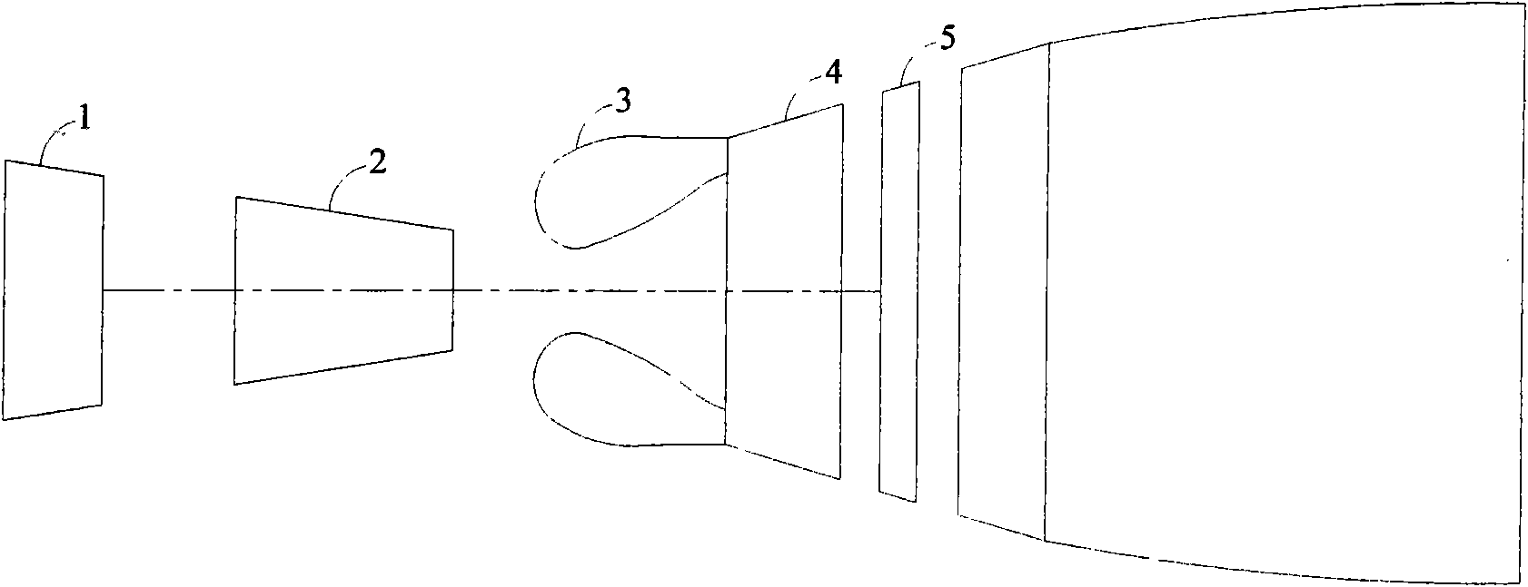
[0029] figure 1 It is a schematic diagram of the engine structure, including a low-pressure compressor 1, a high-pressure compressor 2, a combustion chamber 3, a high-pressure turbine 4 and a low-pressure turbine 5. When the engine is working, the air is compressed by the low-pressure compressor 1 and enters the high-pressure compressor 2. The high-pressure air then enters the combustion chamber 3 to burn with fuel. The high-temperature and high-pressure gas formed after combustion enters the high-pressure turbine 4 and low-pressure turbine 5, and passes through the turbine. Work is done to drive the high-pressure compressor 2 and the low-pressure compressor 1 respectively.

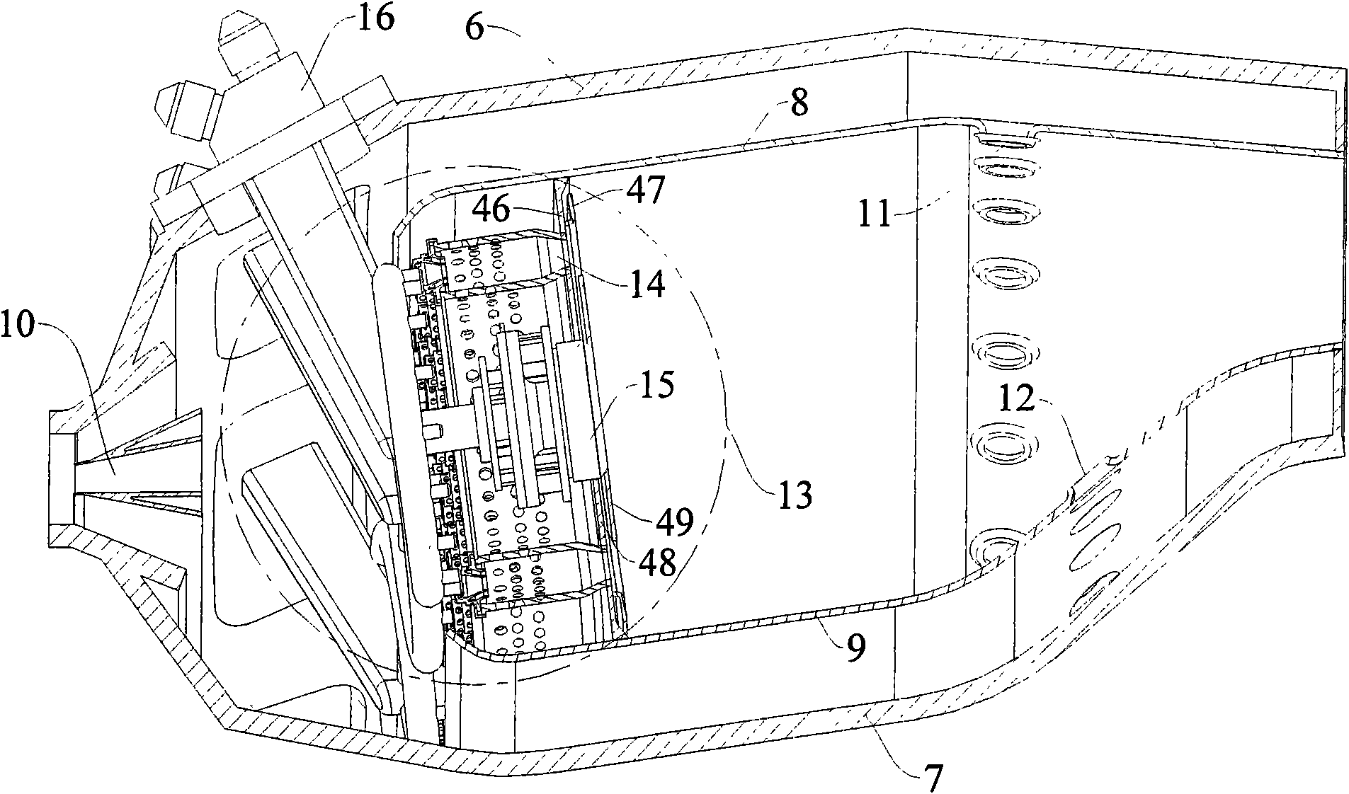
[0030] Such as figure 2 As shown, the combustion chamber 3 adopts a single-annular cavity structure, and the casing 6 outside the combustion chamber and the casing 7 inside the combustion chamber constitute the outer contour of the combustion chamber, and are connected with the high-pressure compressor ...


PUM


Abstract

The invention relates to a low-pollution combustion chamber provided with a premixing and pre-evaporating ring pipe, which adopts a single-ring cavity structure and consists of a combustion chamber outer casing, a combustion chamber inner casing, an outer flame tube, an inner flame tube and a combustion chamber head part, wherein air used for combustion completely enters into the flame tubes from the combustion chamber head part; the scheme of fractional combustion can be adopted, and pre-combustion stage and a main-combustion stage are divided; the main-combustion stage comprises the premixing and pre-evaporating ring pipe, a main-combustion stage nozzle and a main-combustion stage swirler; fuel oil is evaporated and mixed inside the premixing and pre-evaporating ring pipe and then enters into the flame tubes after forming even mixed combustible gas, belonging to premixed combustion; a fuel nozzle is used for supplying the fuel oil for the pre-combustion stage and the main-combustion stage; the stable working range of the combustion chamber is mainly controlled by the pre-combustion stage, so that the stable combustion can be ensured to be carried out in the combustion chamber within wider working range, and a stable ignition source can be provided for the main-combustion stage; the pollution emission is mainly controlled by the main-combustion stage, and the equivalent weight ration of the premixed gas of the main-combustion stage can be controlled within the low-pollution combustion range, so that the pollution emission of the whole combustion chamber cam be ensured to be greatly reduced. The premixing and pre-evaporating structure has small size, simple structure and modularized characteristic, can reduce the pollution emission of the combustion chamber of an aircraft engine, and ensures good combustion stability.

Description

technical field [0001] The invention relates to a low-pollution combustion chamber of an aviation gas turbine using a premixed pre-evaporation ring pipe as a main combustion stage, which can reduce pollution emissions and ensure efficient and stable operation of the combustion chamber. Background technique [0002] The basic performance and structural distribution of modern aero-engine combustors have reached a fairly high level, but there are still a lot of problems and challenges for modern aero-engine combustors. The development and application of new materials, new processes, new structures, and new concepts It is the source to ensure its continuous progress. [0003] The main development trend of modern aero-engine combustors is low-pollution combustion. Aeroengine combustors must meet increasingly stringent aeroengine pollution emission standards. The currently adopted CAEP4 (Committee on Aviation Environmental Protection) standard has very strict requirements, espec...

Claims


Application Information

Patent Timeline
Patent Type & Authority Applications(China)
IPC IPC(8): F23R3/52F23R3/58F23R3/32F23R3/38
Inventor 张弛林阳林宇震许全宏刘高恩
Owner BEIHANG UNIV
Why Eureka
Try Eureka