

Ice and snow rapid melting anti-sliding device based on snowy slope parking
An anti-rolling car and slope technology, which is applied to the buildings where cars are parked, vehicle parts, transportation and packaging, etc., can solve the problems of inability to apply front wheel fixation, inability to automatically force the fixed connection, and inability to automatically strengthen the fixation effect, etc. Achieve good fixing effect, increase contact area and enhance fixing effect
- Summary
- Abstract
- Description
- Claims
- Application Information
AI Technical Summary
Problems solved by technology
Method used
Image

Examples
Embodiment
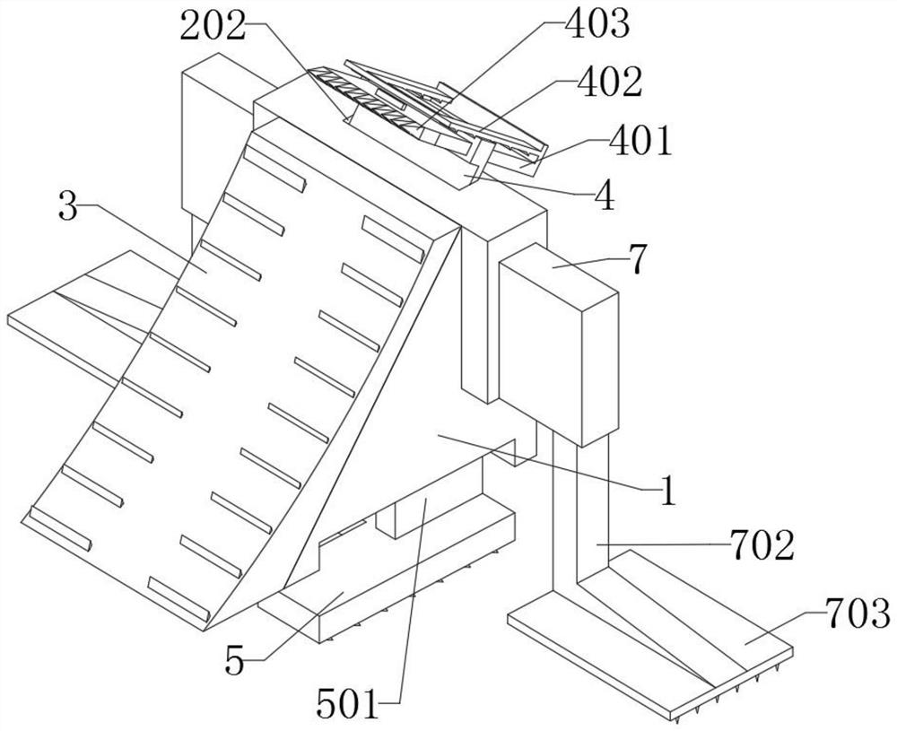
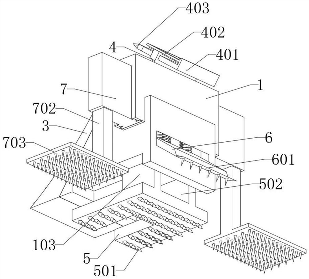
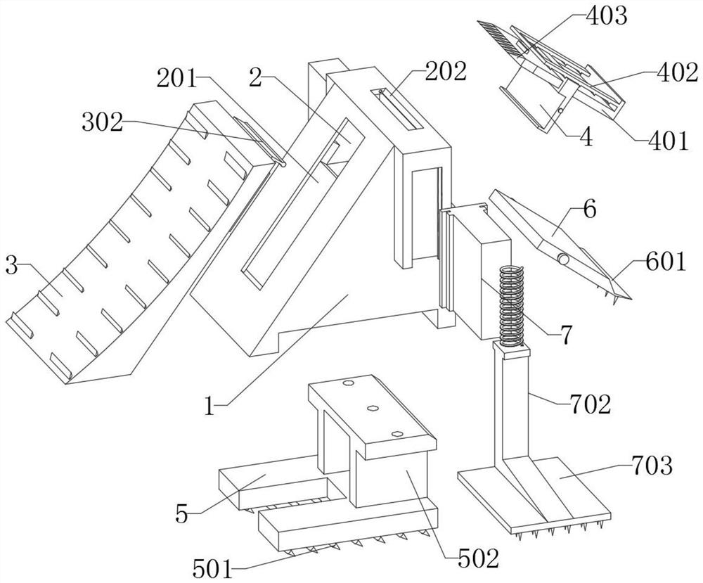
[0035] as attached figure 1 to attach Figure 9 Shown:
[0036] The present invention provides an ice and snow rapid melting anti-rolling device based on parking on a slope in a snowy day, including a main body 1, an inner tank 2, a force receiving member 3, a turning plate 4, a bottom member 5, an auxiliary plate 6 and an installation block 7; the main body 1 is a triangular shape structure, and the front end of the main body 1 is an arc-shaped structure, and there are two rectangular bumps on both sides of the main body 1; the inner groove 2 is set on the inner top of the main body 1; The guide block 301 of the power part 3 is embedded in the guide groove 201; the bottom part 5 is embedded in the bottom groove 103, and the limit part 501 of the bottom part 5 is installed in the force groove 101; The top of the stopper 501 is in contact with the bottom end of the spring, and a guide rod is inserted into the inside of the round hole of the stopper 501; Inside the connection...
PUM
 Abstract
Description
Claims
Application Information