
Ventilation device for tunnel construction

A ventilation device and tunnel construction technology, which is applied in mine/tunnel ventilation, mining devices, safety devices, etc. It can solve the problems of working environment impact on the construction surface, noise, and inability to reduce dust and dust during construction in the tunnel, so as to facilitate recycling and maintenance Utilization ability, avoiding secondary damage, and improving the effect of sustainable utilization ability

Pending Publication Date: 2021-06-11
凌振英
View PDF6 Cites 0 Cited by
  • Summary
  • Abstract
  • Description
  • Claims
  • Application Information

AI Technical Summary

Problems solved by technology

[0004] In order to better supply the air seeping out of the tunnel, it is generally necessary to bury a long ventilation pipe. The weight of the ventilation pipe itself is likely to bring a heavy load to the supporting point at the top of the tunnel, and when the pipe falls due to construction vibration , It is easy to drop and pull the pipes, causing the pipes on both sides to break, crack and break. The integrated pipes cannot be repaired quickly, which affects the repeatability. At the same time, the air circulation in the pipes is likely to generate a lot of noise, which affects the safety of air transmission. At the same time, the construction dust in the tunnel cannot be reduced during the ventilation of the tunnel, which has a great impact on the working environment of the construction surface and cannot well meet the needs of use.

Method used


Image

  • Ventilation device for tunnel construction
  • Ventilation device for tunnel construction
  • Ventilation device for tunnel construction

Examples


Embodiment Construction

[0036] The following will clearly and completely describe the technical solutions in the embodiments of the present invention with reference to the accompanying drawings in the embodiments of the present invention. Obviously, the described embodiments are only some, not all, embodiments of the present invention.

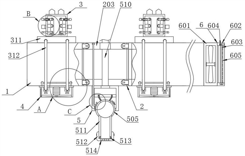
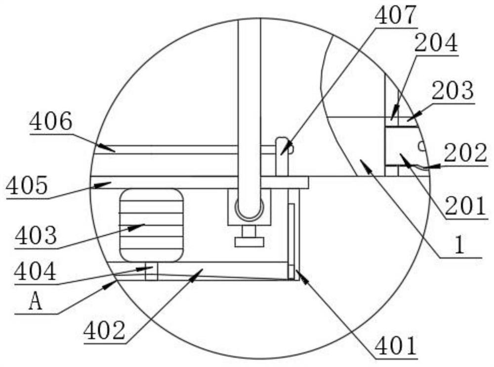
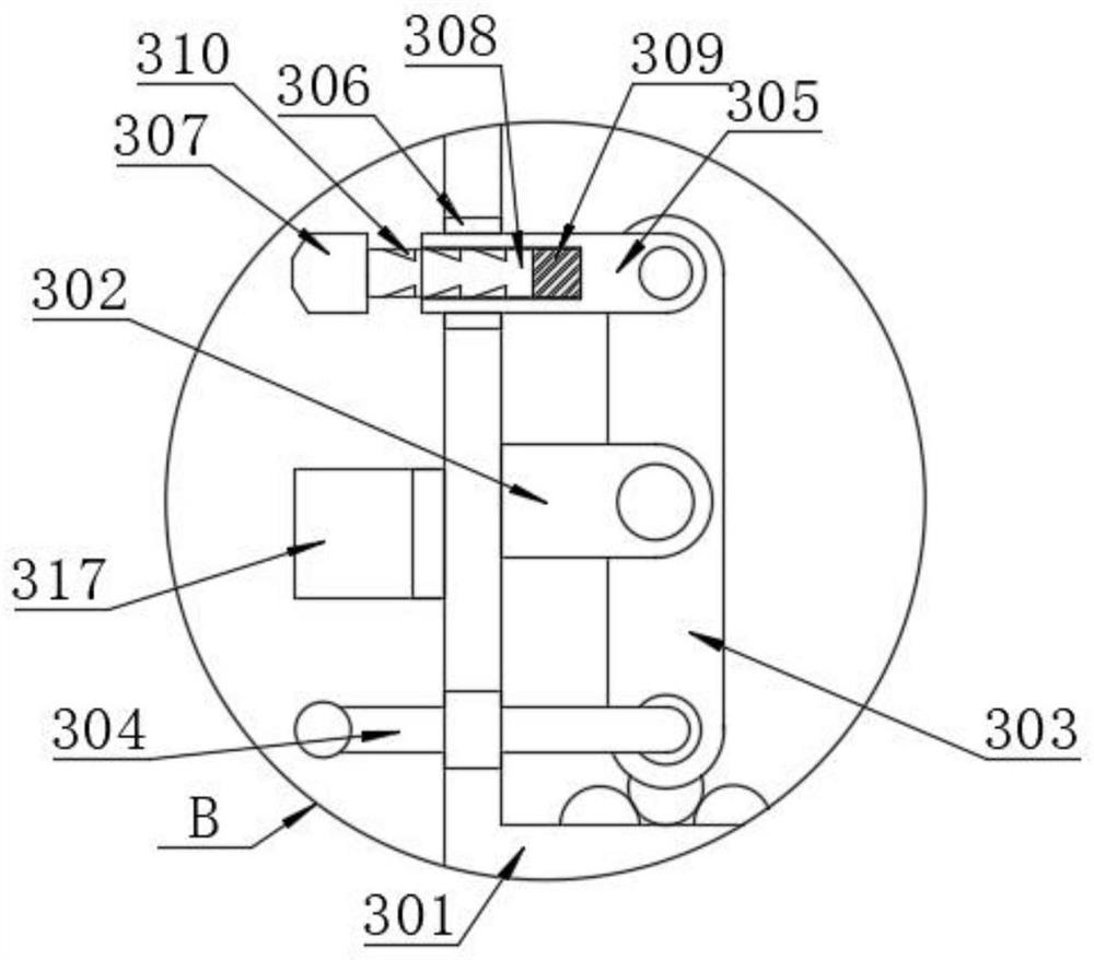
[0037] refer to Figure 1-10 , a ventilation device for tunnel construction, including a ventilation pipe 1, the outer wall of the ventilation pipe 1 is provided with an installation mechanism 3, which can improve the assembly efficiency, and the installation mechanism 3 is fixedly clamped to the pre-installed opening in the inner cavity of the tunnel. In the tank body, the bottom of the installation mechanism 3 is provided with a buffer mechanism 4, the buffer mechanism 4 is located at the bottom of the ventilation pipe 1 and the installation mechanism 3, and a dust suppression mechanism 5 is movably connected between the ventilation pipe 1 through a limit mechanism ...


PUM


Abstract

The invention discloses a ventilation device for tunnel construction. The ventilation device comprises a ventilation pipe, wherein a mounting mechanism is arranged on the outer side wall of the ventilation pipe in a sleeving manner; the mounting mechanism is fixedly clamped in a preset groove body formed in an inner cavity of a tunnel; a buffer mechanism is arranged at the bottom of the mounting mechanism in a sleeving manner; and the buffer mechanism is positioned at the bottoms of the ventilation pipe and the mounting mechanism. According to the ventilation device disclosed by the invention, the fallen ventilation pipe is quickly separated from the ventilation pipe of which the two sides are not vibrated, so that secondary damage caused by falling and pulling is effectively avoided; through modular assembly, the sustainable utilization capacity is obviously improved, the stability of lightweight hanging and fixing is guaranteed while the disassembly and maintenance efficiency of a steel cable is guaranteed, and the air conveying requirements of the ventilation pipes with different lengths are met; and through cooperation of a noise reduction plate, noise generated when air circulates in the ventilation pipe is effectively reduced, and meanwhile, the falling impact can be absorbed through a buffer air bag to guarantee the safety of the ventilation pipe during falling, so that subsequent recovery and maintenance are facilitated.

Description

technical field [0001] The invention relates to the technical field of tunnel construction equipment, in particular to a ventilation device for tunnel construction. Background technique [0002] A tunnel is an engineering building buried in the ground, and it is a form of human use of underground space. Tunnels can be divided into traffic tunnels, hydraulic tunnels, municipal tunnels, mine tunnels, military tunnels, etc. [0003] During tunnel construction, it is generally necessary to use ventilation devices to ventilate and supply oxygen deep in the tunnel to ensure the safety of ventilation in tunnel construction. Methods such as ventilation are used to create the required air environment for the space of tunnels and underground construction projects. Different tunnels and Underground projects have their own ventilation requirements. Due to the different geographical and climatic conditions, building structures and internal production processes, the ventilation technical...

Claims


Application Information

Patent Timeline
Patent Type & Authority Applications(China)
IPC IPC(8): E21F1/00E21F1/04E21F1/08E21F17/02E21F5/04F16L55/033
CPCE21F1/006E21F1/04E21F1/08E21F17/02E21F5/04F16L55/033
Inventor 凌振英
Owner 凌振英
Learn More