[0075] The present invention will be further described below in conjunction with the accompanying drawings and embodiments.
[0076] It should be pointed out that the following detailed description is exemplary and is intended to provide further explanation to the present application. Unless defined otherwise, all technical and scientific terms used herein have the same meaning as commonly understood by one of ordinary skill in the art to which this application belongs.
[0077] It should be noted that the terminology used here is only for describing specific implementations, and is not intended to limit the exemplary implementations according to the present application. As used herein, unless the context clearly dictates otherwise, the singular is intended to include the plural, and it should also be understood that when the terms "comprising" and/or "comprising" are used in this specification, they mean There are features, steps, operations, means, components and/or combinations thereof.
[0078] like Figure 5 As shown, this embodiment provides a method for monitoring anomaly metering of specific users, which specifically includes the following steps:
[0079] Collect data including three-phase voltage, current and power factor curves at the target metering point and the reference metering point at the same time;
[0080] Calculate the transformer impedance according to the short-circuit test parameters of the target transformer;
[0081] According to the voltage, current and power factor at the target metering point, combined with the transformer impedance, and based on the three-phase vector relationship between the high voltage side and the low voltage side of the transformer, calculate the corrected voltage amplitude, corrected voltage angle and voltage phase at the target metering point offset;
[0082] According to the triangular cosine theorem, calculate the line voltage and phase voltage on the high voltage side of the target metering point;
[0083] Calculate the high-voltage side phase voltage of the reference metering point according to the above steps;
[0084] Construct the evaluation equation according to the high-voltage side voltage of the target metering point and the reference metering point;
[0085] Adjust the current coefficient of the target metering point, recalculate the phase voltage of the high-voltage side of the target metering point, and find the minimum value of the evaluation equation;
[0086] When the value of the evaluation equation is the smallest, judge the size of the current coefficient at this time, if the difference between the current coefficient and 1 is less than the preset value, that is, the current coefficient is close to 1, then it is determined that the metering device at the target measurement point is normal; Otherwise, it is determined that the current acquisition at the target metering point is abnormal.
[0087] Preferably, there is a certain causal relationship between the user voltage curve and the current curve for high supply and low consumption. Usually, when the user load current increases, the voltage decreases, and when the user's three-phase load is unbalanced, the three-phase voltage is also unbalanced. The change of the voltage at the low-voltage side of the transformer with the load is the external characteristic of the transformer. By analyzing whether the relationship between the voltage and the load meets the external characteristics of the transformer, it can be inferred whether there is an abnormality or power theft in the metering device.
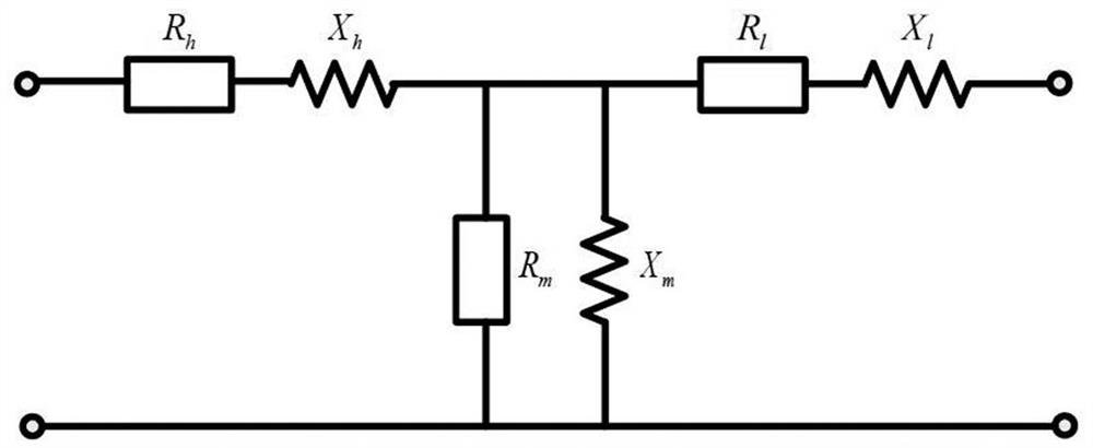
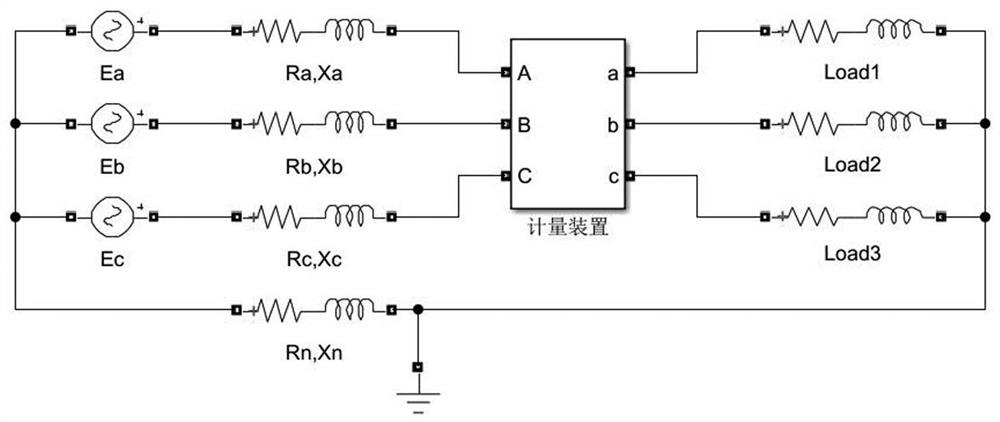
[0088] The transformer equivalent circuit is T-shaped, such as figure 1 As shown, R m 、X m is the excitation impedance, R h 、X h is the high voltage side leakage resistance, R 1 、X 1 is the low voltage side leakage impedance. Generally, the excitation current is much smaller than the user's normal load current, and has little effect on the line voltage drop. R m 、X m neglect. R h 、X h , R 1 、X 1 It can be uniformly attributed to the high-voltage side or low-pressure side, which is uniformly expressed as R below t 、X t. Known transformer capacity, R t 、X t It is known that the difference between different models is small. 50kVA-400kVA transformer Z t Converted to the high-voltage side, it is about 10 to 100 ohms, which is generally larger than the impedance of the medium-voltage line, so the R t 、X t The resulting voltage drop is greater than that caused by the external wiring. Set the high-voltage side voltage (the value is attributed to the low-voltage side, which will be handled in this way below) as E a ,E b and E c , available as figure 2 The three-phase equivalent circuit for high-supply and low-supply users is shown. What needs to be added is that the three-phase transformer also has zero-sequence impedance R n 、X n , mainly related to the wiring group and magnetic circuit structure. The impedance value of Yyn0 type is much larger than that of Dyn11 type, and the individual discreteness is large.
[0089] In this embodiment, the reference metering point is an adjacent specific variable or common variable metering point located on the same line as the target metering point.
[0090] In this embodiment, the calculation of the transformer impedance according to the short-circuit test parameters of the target transformer is specifically:
[0091] Calculate the equivalent resistance and equivalent reactance of the transformer;
[0092] The equivalent resistance of the transformer is calculated by the short-circuit loss of the transformer, using the following formula:
[0093]
[0094] In the formula, R T is the equivalent resistance of the transformer, U N is the rated voltage of the transformer, S N is the rated capacity of the transformer, P k is the short-circuit loss of the transformer;
[0095] The equivalent reactance of the transformer is determined by the transformer equivalent impedance Z T and equivalent resistance R T Calculated using the following formula:
[0096]
[0097] In this embodiment, the transformer equivalent impedance Z T Calculated using the following formula:
[0098]
[0099] In the formula, U k % is the short-circuit voltage drop percentage of the transformer, U N is the rated voltage of the transformer, I N is the rated current of the transformer.
[0100] In this embodiment, according to the voltage, current and power factor at the target metering point, combined with the transformer impedance, and based on the three-phase vector relationship between the high voltage side and the low voltage side of the transformer, the corrected voltage amplitude and corrected voltage amplitude at the target metering point are calculated. The final voltage angle and voltage phase offset are specifically:
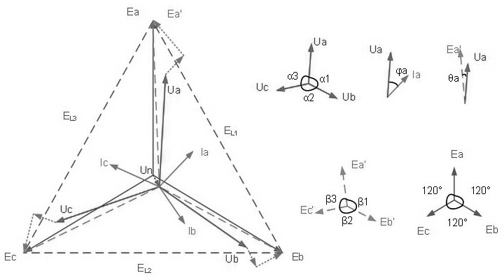
[0101] The relationship between voltage amplitude and phase deviation caused by transformer impedance is as follows: Figure 4 As shown, use the following formula to calculate the corrected voltage amplitude of the target metering point:
[0102]
[0103]
[0104]
[0105] In the formula, U a , U b and U c is the three-phase voltage collected at the target metering point, I a , I b and I c is the three-phase current, and is the angle between the voltage and current of the three phases (that is, the power angle), E′ a , E' b and E' c The correction voltage is based on the grounding point of the low-voltage side of the transformer as the reference point; X T is the equivalent reactance of the transformer, R T is the equivalent impedance of the transformer;
[0106] refer to image 3 The three-phase vector conversion relationship between the high-voltage side and the low-voltage side of the transformer, the corrected voltage phase displacement of the target metering point is calculated using the following formula:
[0107]
[0108]
[0109]
[0110] In the formula, θ a , θ b and θ c is the voltage phase offset;
[0111] Use the following formula to calculate the corrected voltage angle of the target metering point:
[0112] beta 1 = α 1 +θ a -θ b;
[0113] beta 2 = α 2 +θ b -θ c;
[0114] beta 3 = α 3 +θ c -θ a;
[0115] In the formula, β 1 , β 2 and beta 3 is the corrected three-phase voltage angle, α 1 、α 2 and alpha 3 is the included angle of the original three-phase voltage.
[0116] In this embodiment, according to the triangular cosine theorem, the calculation of the line voltage on the high voltage side and the phase voltage on the high voltage side of the target metering point is specifically:
[0117] Use the following formula to calculate the high voltage side line voltage E of the target metering point L1 ,E L2 and E L3 :
[0118] E. L1 2 =E' a 2 +E' b 2 -2E′ a E' b cosβ 1;
[0119] E. L2 2 =E' b 2 +E' c 2 -2E′ b E' c cosβ 2;
[0120] E. L3 2 =E' c 2 +E' a 2 -2E′ c E' a cosβ 3;
[0121] In the formula, E' a , E' b and E' c The correction voltage is based on the grounding point of the low-voltage side of the transformer as the reference point; β 1 , β 2 and beta 3 is the corrected three-phase voltage angle; if the high-voltage side of the target transformer is delta-connected, further solve its phase voltage;
[0122] Use the relationship of the following formula to calculate the high-voltage side phase voltage E of the target metering point a ,E b and E c :
[0123] E. L1 2 =E a 2 +E b 2 +E a E. b;
[0124] E. L2 2 =E b 2 +E c 2 +E b E. c;
[0125] E. L3 2 =E c 2 +E a 2 +E c E. a.
[0126] For the high-voltage side, if the high-voltage side of the transformer is delta-connected, that is, the connection mode is Dyn11, the line voltage and phase voltage of the high-voltage side are equal, which is E in the above formula a ,E b and E c; If the high-voltage side of the transformer is connected in star form, that is, the connection mode is Yyn0, then the line voltage of the high-voltage side of the transformer is E in the above formula L1 ,E L2 and E L3.
[0127] In this embodiment, the evaluation equation is as follows:
[0128] f p (k)=(E 1 -k r E. ref1 ) 2 +(E 2 -k r E. ref2 ) 2 +(E 3 -k r E. ref3 ) 2;
[0129] where k r It is the ratio of the line voltage of the target metering point to the reference metering point. It is related to the tap connected to the high-voltage side of the transformer and can be switched by a tap changer. Therefore, it is set as an unknown quantity and optimized for solution.
[0130] E. 1 ,E 2 ,E 3 is the three-phase line voltage of the target metering point, E ref1 ,E ref2 ,E ref3 is the three-phase line voltage of the reference metering point. If the reference metering point is high-supply and high-metering, the line voltage at the reference metering point is directly taken; if the reference metering point is high-supply and low-metering, it needs to be converted as described above The line voltage to the high voltage side is calculated according to the previous formula and description.
[0131] Since the transformer at the target metering point and the transformer at the reference metering point are involved at this time, when calculating, E 1 and E ref1 Must be the same phase, due to factors such as on-site construction, it is impossible to determine whether they are the same phase. Similarly, the wiring mode of the high-voltage side cannot be directly queried in the system, so the exhaustive method is adopted, and there are 6 possible combinations (ABC, BCA, CAB, ACB, BAC, CBA), and there are 2 wiring modes for each transformer. possible (triangle or star), so F p (k) There are 24 possibilities in total.
[0132] In this embodiment, the current coefficient of the target metering point is calculated using the following formula:
[0133] I a =k a I' a;
[0134] I b =k b I' b;
[0135] I c =k c I'c;
[0136] In the formula, I a , I b , I c is the actual current value of the target metering point, I′ a , I' b , I' c is the current measurement value of the target metering point, k a 、k b 、k c is the current coefficient.
[0137] In this embodiment, the searching for the minimum value of the evaluation equation belongs to the optimization of a discontinuous nonlinear programming problem, which can be solved by an intelligent algorithm or a corresponding solver.
[0138] This embodiment also provides a system for monitoring anomalies in metering of special variable users, including a special variable metering device, a power consumption information collection system, a memory, and a processor;
[0139] The electricity consumption information collection system is used to collect data including voltage and current curves of the special variable metering device, and transmit them to the processor;
[0140] A computer program that can be run by the processor is stored in the memory, and when the processor is running the computer program, the above-mentioned method steps are realized.
[0141] This embodiment also provides a computer-readable storage medium, on which computer program instructions that can be executed by a processor are stored. When the processor executes the computer program instructions, the above-mentioned method steps can be implemented.
[0142] Those skilled in the art should understand that the embodiments of the present application may be provided as methods, systems, or computer program products. Accordingly, the present application may take the form of an entirely hardware embodiment, an entirely software embodiment, or an embodiment combining software and hardware aspects. Furthermore, the present application may take the form of a computer program product embodied on one or more computer-usable storage media (including but not limited to disk storage, CD-ROM, optical storage, etc.) having computer-usable program code embodied therein.
[0143] The present application is described with reference to flowcharts and/or block diagrams of methods, apparatus (systems), and computer program products according to embodiments of the present application. It should be understood that each procedure and/or block in the flowchart and/or block diagram, and a combination of procedures and/or blocks in the flowchart and/or block diagram can be realized by computer program instructions. These computer program instructions may be provided to a general purpose computer, special purpose computer, embedded processor, or processor of other programmable data processing equipment to produce a machine such that the instructions executed by the processor of the computer or other programmable data processing equipment produce a in real process Figure 1 process or multiple processes and/or boxes Figure 1 means for the function specified in one or more boxes.
[0144] These computer program instructions may also be stored in a computer-readable memory capable of directing a computer or other programmable data processing apparatus to operate in a specific manner, such that the instructions stored in the computer-readable memory produce an article of manufacture comprising instruction means, the instructions The device is implemented in the process Figure 1 process or multiple processes and/or boxes Figure 1 function specified in one or more boxes.
[0145] These computer program instructions can also be loaded onto a computer or other programmable data processing device, causing a series of operational steps to be performed on the computer or other programmable device to produce a computer-implemented process, thereby instructions are provided for implementing the flow in Figure 1 process or multiple processes and/or boxes Figure 1 steps of the function specified in the box or boxes.
[0146] The above is only a preferred embodiment of the present invention, and is not intended to limit the present invention to other forms. Any skilled person who is familiar with this profession may use the technical content disclosed above to change or modify the equivalent of equivalent changes. Example. However, any simple modifications, equivalent changes and modifications made to the above embodiments according to the technical essence of the present invention without departing from the content of the technical solution of the present invention still belong to the protection scope of the technical solution of the present invention.