Camera device, electronic equipment, depth-of-field detection method and depth-of-field detection device

A camera and detection unit technology, applied in the field of communication, can solve problems such as difficult to overcome multi-machine interference, and achieve the effect of avoiding multi-machine interference

Active Publication Date: 2021-06-11
VIVO MOBILE COMM CO LTD
View PDF6 Cites 1 Cited by
  • Summary
  • Abstract
  • Description
  • Claims
  • Application Information

AI Technical Summary

Problems solved by technology

[0004] The purpose of the embodiments of the present application is to provide a camera device, electronic equipment, depth of field detection method and device, which can solve the problem that existing electronic equipment is difficult to overcome multi-camera interference during depth of field detection

Method used


Image

  • Camera device, electronic equipment, depth-of-field detection method and depth-of-field detection device
  • Camera device, electronic equipment, depth-of-field detection method and depth-of-field detection device
  • Camera device, electronic equipment, depth-of-field detection method and depth-of-field detection device

Examples


Embodiment Construction

[0034] The following will clearly and completely describe the technical solutions in the embodiments of the present application with reference to the drawings in the embodiments of the present application. Obviously, the described embodiments are part of the embodiments of the present application, not all of them. Based on the embodiments in this application, all other embodiments obtained by persons of ordinary skill in the art without creative efforts fall within the protection scope of this application.

[0035] The terms "first", "second" and the like in the specification and claims of the present application are used to distinguish similar objects, and are not used to describe a specific sequence or sequence. It should be understood that the terms so used are interchangeable under appropriate circumstances such that the embodiments of the application can be practiced in sequences other than those illustrated or described herein, and that references to "first," "second," et...


PUM


Abstract

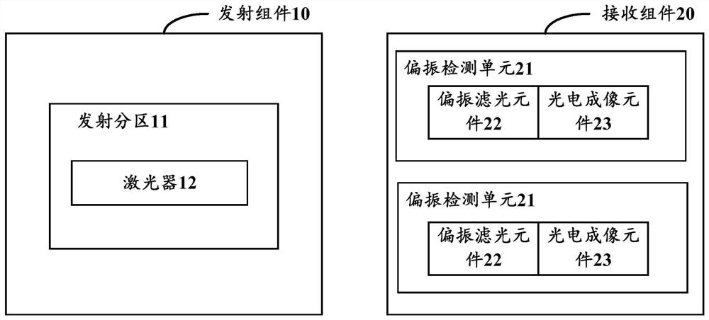
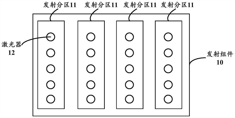
The invention discloses a camera device, electronic equipment, and a depth-of-field detection method and device, belongs to the technical field of communication, and can solve the problem that the existing electronic equipment is difficult to overcome multi-machine interference during depth-of-field detection. The device comprises a transmitting assembly and a receiving assembly. The transmitting assembly comprises at least one transmitting subarea, and each transmitting subarea is provided with at least one laser used for transmitting polarized light with a first specified polarization angle; and the receiving assembly comprises a plurality of polarization detection units, each polarization detection unit comprises a polarization filtering element and a photoelectric imaging element, and when the receiving assembly receives the polarized light of the first polarization angle, the polarized light of the first polarization angle only can pass through the polarization filtering element corresponding to the first polarization angle and irradiates the photoelectric imaging element. According to the scheme, the possibility that the receiving assembly receives other light rays (light rays reflected based on the light rays emitted by other emitting assemblies) can be greatly reduced, so that the situation of multi-machine interference can be avoided.

Description

technical field [0001] The present application belongs to the technical field of communication, and in particular relates to a camera device, an electronic device, a method and a device for detecting depth of field. Background technique [0002] With the gradual popularization of augmented reality (Augmented Reality, AR), virtual reality (Virtual Reality, VR) and related three-dimensional (three dimensional, 3D) applications, more and more equipment manufacturers are equipped with 3D cameras on their products to support related application. The current mainstream 3D camera adopts the Time of Flight (TOF) scheme, which calculates the distance from the device to a certain point in the environment through the time of flight of light, so as to obtain the depth of field information of the environment. [0003] In the existing scheme, when there are multiple transmitters working in the same environment, the light emitted by multiple transmitters in the environment may be received...

Claims


Application Information

Patent Timeline
Patent Type & Authority Applications(China)
IPC IPC(8): H04N5/225G03B13/30G06T7/514
CPCG03B13/30G06T7/514H04N23/55
Inventor 聂磊
Owner VIVO MOBILE COMM CO LTD
Why Eureka
Try Eureka