
Laser welding mechanism for metal support

A laser welding and metal bracket technology, which is applied in laser welding equipment, welding equipment, metal processing equipment and other directions, can solve the problems of metal debris splashing, insufficient manual positioning accuracy, and working environment pollution.

Inactive Publication Date: 2021-06-15
常州美通备品车辆配件有限公司
View PDF0 Cites 0 Cited by
  • Summary
  • Abstract
  • Description
  • Claims
  • Application Information

AI Technical Summary

Problems solved by technology

[0003] When the metal bracket is assembled, it is necessary to open a round hole on the square tube, and then insert a metal round tube into the round hole on the square tube, and weld the metal round tube to the square tube. The previous welding methods include plasma welding or electric current. Welding, but these welding methods will grow very high arcs, and these arcs will also cause metal debris to splash, which also pollutes the working environment to a certain extent. Using laser slow welding will not produce debris splashes, and when welding It is also necessary to manually position the steel pipe, and the accuracy of manual positioning is not high enough

Method used


Image

  • Laser welding mechanism for metal support
  • Laser welding mechanism for metal support
  • Laser welding mechanism for metal support

Examples


Embodiment Construction

[0026] In order to make the object, technical solution and advantages of the present invention clearer, the present invention will be further described in detail below in conjunction with the accompanying drawings and embodiments. It should be understood that the specific embodiments described here are only used to explain the present invention, not to limit the present invention.

[0027] In describing the present invention, it should be understood that the terms "longitudinal", "transverse", "upper", "lower", "front", "rear", "left", "right", "vertical", The orientations or positional relationships indicated by "horizontal", "top", "bottom", "inner", "outer", etc. are based on the orientations or positional relationships shown in the drawings, and are only for the convenience of describing the present invention, rather than indicating or It should not be construed as limiting the invention by implying that a referenced device or element must have a particular orientation, be...


PUM


Abstract

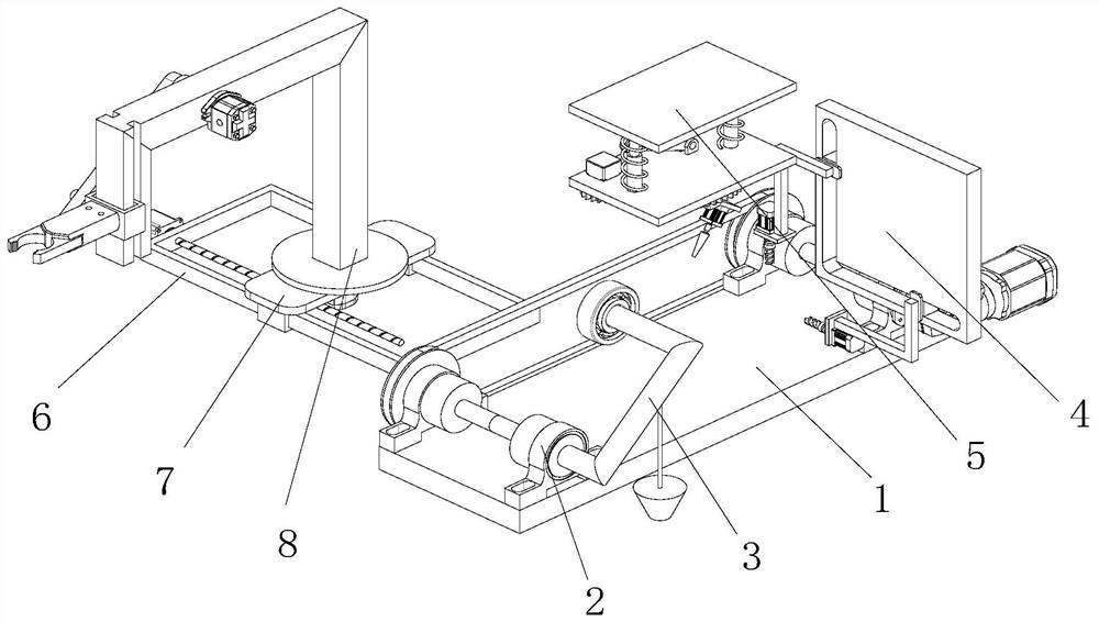
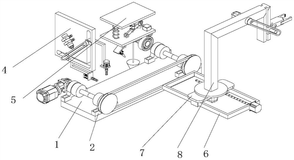
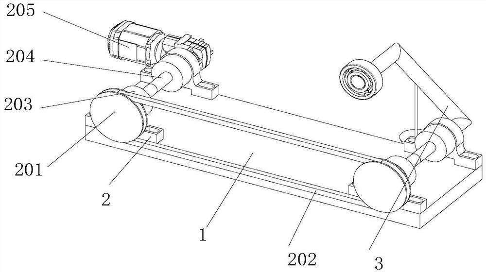
The invention discloses a laser welding mechanism for a metal support, and belongs to the field of support welding. The laser welding mechanism comprises a base table plate; four carrying shaft seats are arranged at the top end of the base table plate; the four carrying shaft seats are respectively arranged at four corners of the base table plate; every two carrying shaft seats form a group; one side of each carrying shaft seat is provided with a carrying column; annular grooves are formed on the side wall of the carrying column, and the ends of the annular grooves are in butt joint; a carrying motor is fixedly installed on the side wall of one carrying shaft seat; the side walls of carrying rotary discs are fixedly connected with the carrying columns; the two carrying rotary discs are connected through a carrying belt; pressing arms are further installed on one sides of the carrying shaft seats; the end of each pressing arm is inserted into the inner side of the carrying shaft seat; the pressing arms are rotatably connected with the carrying shaft seats; the other end of each pressing arm is provided with a pressing wheel; the middle of the pressing arm is provided with a drooping line; and the bottom end of the drooping line is provided with a lead block. Automatic welding can be achieved conveniently.

Description

technical field [0001] The invention relates to the field of bracket processing, in particular to a laser welding mechanism for metal brackets. Background technique [0002] With the development of industrial technology, modern mechanical processing has become more and more perfect, and a lot of brackets need to be used when mechanical assembly or processing is added. Since the current mechanical processing is mass-produced and produced, large factories Batches of metal brackets are needed. In the sheet metal processing industry, the brackets used are made of square tubes and round tubes; [0003] When assembling the metal bracket, it is necessary to open a round hole on the square tube, and then insert a metal round tube into the round hole on the square tube to weld the metal round tube to the square tube. The previous welding methods include plasma welding or electric current. Welding, but these welding methods will grow very high arcs, and these arcs will also cause met...

Claims


Application Information

Patent Timeline
Patent Type & Authority Applications(China)
IPC IPC(8): B23K26/21B23K26/02B23P23/04
CPCB23K26/02B23P23/04B23K26/21
Inventor 旷鹏华
Owner 常州美通备品车辆配件有限公司
Learn More