Optical fiber cable surface snap ring mounting device based on new-generation information technology

An information technology and optical fiber cable technology, which is applied in the field of snap ring installation devices on the surface of optical fiber cables, can solve the problems of inconvenient installation and operation of snap rings and low installation efficiency, and achieve the effects of automatic installation, high installation efficiency, and convenient installation and operation

Inactive Publication Date: 2021-06-15
广州普俞电子商务有限公司
View PDF8 Cites 0 Cited by
  • Summary
  • Abstract
  • Description
  • Claims
  • Application Information

AI Technical Summary

Problems solved by technology

[0005] Aiming at the deficiencies of the prior art, the present invention provides a device for installing snap rings on the surface of optical fiber cables based on a new generation of information technology, which can automatically install the snap rings on the surface of optical fiber cables. The advantage of high installation efficiency solves the problems of inconvenient installation and operation of the snap ring on the surface of the existing optical fiber cable and low installation efficiency

Method used


Image

  • Optical fiber cable surface snap ring mounting device based on new-generation information technology
  • Optical fiber cable surface snap ring mounting device based on new-generation information technology
  • Optical fiber cable surface snap ring mounting device based on new-generation information technology

Examples


Embodiment Construction

[0026] The following will clearly and completely describe the technical solutions in the embodiments of the present invention with reference to the accompanying drawings in the embodiments of the present invention. Obviously, the described embodiments are only some, not all, embodiments of the present invention. Based on the embodiments of the present invention, all other embodiments obtained by persons of ordinary skill in the art without making creative efforts belong to the protection scope of the present invention.

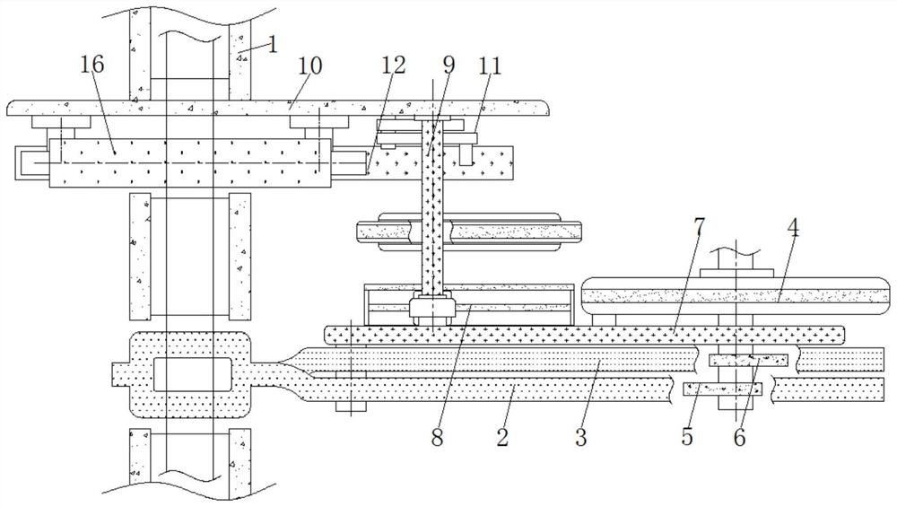
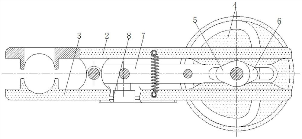
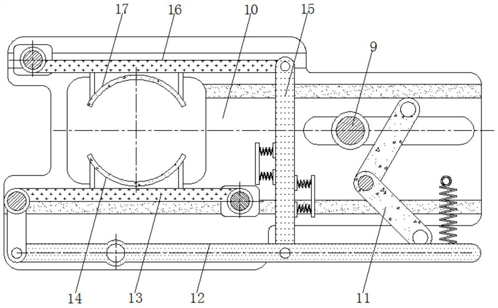
[0027] see Figure 1-4 , a clasp ring installation device on the surface of an optical fiber cable based on a new generation of information technology, including a conveying device 1 for conveying the optical fiber cable, the surface of the conveying device 1 is provided with a feeding plate 2, and the upper surface of the feeding plate 2 is provided with Feeding port, between the feeding plate 2 and the mounting plate 3 is designed with a movable shaft and a ...


PUM


Abstract

The invention relates to the technical field of optical fiber equipment, and discloses an optical fiber cable surface snap ring mounting device based on a new-generation information technology. The optical fiber cable surface snap ring mounting device comprises a conveying device, a feeding plate is arranged on the surface of the conveying device, a mounting plate is arranged on the lower portion of the feeding plate, a rotating disc is arranged on the side surface of the feeding plate, a first cam is arranged on the side, close to the feeding plate, of the rotating disc, a second cam is arranged on the side face of the first cam, a sliding rod is arranged on the surface of the rotating disc, a sliding rail is arranged on the lower portion of the sliding rod, a push rod is arranged on the surface of the sliding rod, and a side plate is arranged in the conveying device. According to the optical fiber cable surface snap ring mounting device based on the new-generation information technology, through cooperative use of the rotating disc and the sliding rod, cooperative use of the first cam and the feeding plate, cooperative use of the second cam and the mounting plate and cooperative use of the feeding plate and the mounting plate, a snap ring can be automatically placed on the surface of an optical fiber cable, the snap ring mounting operation is convenient, and the mounting efficiency is high.

Description

technical field [0001] The invention relates to the technical field of optical fiber equipment, in particular to a clasp ring installation device on the surface of an optical fiber cable based on a new generation of information technology. Background technique [0002] The development of optical fiber equipment is inseparable from the research and development and application of the new generation of information technology. After the development of the new generation of information technology is completed, it needs the carrying and application of optical fiber equipment. When installing optical fiber equipment, optical fiber cables will be used. When installing the cable, in order to facilitate the installation and fixing of the cable, a snap ring will be installed on the surface of the cable at a certain distance. The installation of the existing snap ring on the surface of the optical fiber cable is done manually by the staff, and the installation operation of the snap ring ...

Claims


Application Information

Patent Timeline
Patent Type & Authority Applications(China)
IPC IPC(8): B23P19/00
CPCB23P19/00B23P19/001
Inventor 张玲妃
Owner 广州普俞电子商务有限公司
Why Eureka
Try Eureka