
Suction and rolling type film sticking machine

A film lamination machine and roll-type technology, which is applied in the field of automatic film lamination equipment, can solve the problems of unsatisfactory defoaming effect, inaccurate film lamination position, and low film lamination precision, and achieve the effect of solving air bubbles, accurate film lamination position, and improving the degree of automation

Active Publication Date: 2021-06-15
深圳市信诚达自动化设备有限公司
View PDF7 Cites 0 Cited by
  • Summary
  • Abstract
  • Description
  • Claims
  • Application Information

AI Technical Summary

Problems solved by technology

[0002]A film laminating machine is a device that pastes a layer of film on the surface of the shell or screen of an electronic product. The existing film laminating machines can be divided into rolling film laminating machines and suction There are two types of film laminating machines. Rolling film laminating machines have the effect of laminating the film, and there will be no air bubbles on the surface of the product, but the precision of the film lamination is not high. When working, the position of the film is often inaccurate, and the yield rate is low; relatively speaking, the suction The film sticking machine has higher precision, which can ensure the precise position of the film. However, it is difficult to avoid the generation of air bubbles in the actual work of the suction film sticking machine. There are some defoaming machines and other equipment on the market. Defoaming effect is not ideal

Method used


Image

  • Suction and rolling type film sticking machine
  • Suction and rolling type film sticking machine
  • Suction and rolling type film sticking machine

Examples


Embodiment Construction

[0028] In order to further illustrate the technical means and technical effects of the present invention, preferred embodiments of the present invention will be described below in conjunction with the accompanying drawings. It should be understood that the specific embodiments described here are only used to explain the present invention, not to limit the present invention. Based on the embodiments of the present invention, all other embodiments obtained by persons of ordinary skill in the art without making creative efforts belong to the protection scope of the present invention.

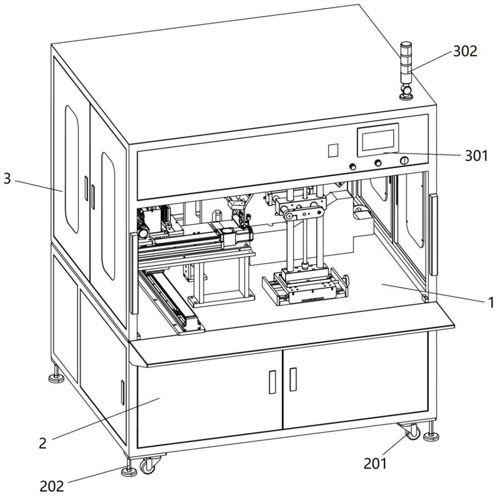
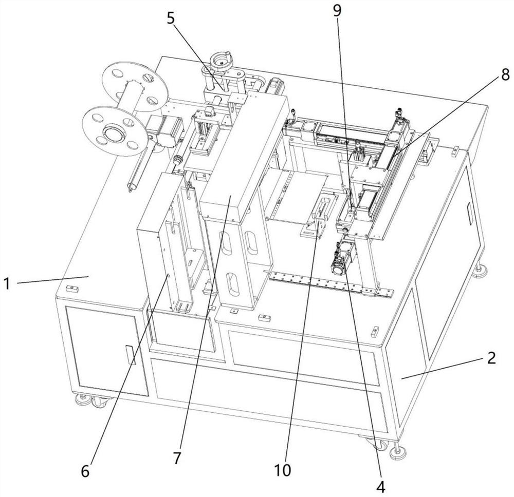
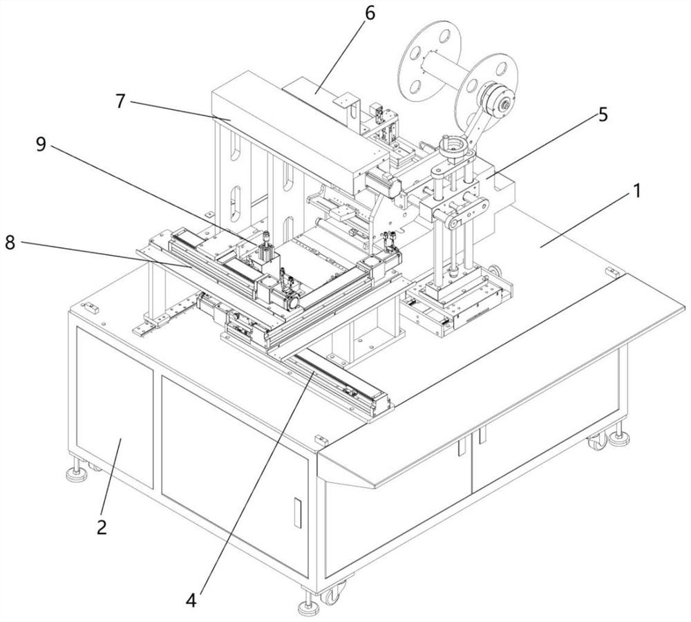
[0029] Such as Figure 1-5 As shown, a suction roll film laminating machine includes a machine 1, a control box 2 and a protective cover 3, the control box 2 is fixed below the machine 1, a controller is fixed inside the control box 2, and the protective cover 3 is set on the On the machine 1, the protective cover 3 is provided with an operation display panel 301, and the top surface of the protec...


PUM


Abstract

The invention discloses a suction and rolling type film sticking machine which comprises a machine table, a controller, a film supply mechanism, a film stripping mechanism and a product feeding mechanism. The film supply mechanism is connected with the film stripping mechanism through a mechanical arm grabbing mechanism, the film stripping mechanism is connected with the product feeding mechanism through a film conveying mechanism, a film sticking mechanism is fixedly arranged on the film conveying mechanism, and the film sticking mechanism comprises a suction sticking mechanism and a rolling sticking mechanism. The film supply mechanism, the film stripping mechanism, the film sticking mechanism, the product feeding mechanism, the mechanical arm grabbing mechanism and the film conveying mechanism are connected with the controller. The product feeding mechanism is used for feeding and discharging products, the mechanical arm grabbing mechanism is used for conveying a film from the film supply mechanism to the film stripping mechanism, and the film conveying mechanism is used for conveying the film from the tail end of the film stripping mechanism to the position above a product jig. Compared with an existing film sticking machine, a suction sticking mode and a rolling sticking mode are integrated, it can be guaranteed that the film sticking position is accurate each time, meanwhile, the problem that bubbles are generated during film sticking is thoroughly solved, and the film sticking efficiency is improved.

Description

technical field [0001] The invention relates to the field of automatic film sticking equipment, in particular to a suction roll film sticking machine. Background technique [0002] The film laminating machine is a device that pastes a layer of film on the surface of the shell or screen of an electronic product. The existing film laminating machines can be divided into two types: rolling film laminating machines and suction film laminating machines. The effect of rolling film laminating machines and products There will be no bubbles on the surface, but the precision of the film is not high. During work, the position of the film is often inaccurate, and the yield rate is low. Relatively speaking, the precision of the suction film laminating machine is higher, which can ensure the precise position of the film, but , It is difficult to avoid the generation of bubbles in the actual work of the suction film laminating machine. There are some defoaming machines and other equipment ...

Claims


Application Information

Patent Timeline
IPC IPC(8): B65B33/02B65B57/06B65B61/00B65B61/24B65H20/00B65H20/16
CPCB65B33/02B65B57/06B65B61/24B65B61/00B65H20/16B65H20/00
Inventor 薛生旺肖宇剑
Owner 深圳市信诚达自动化设备有限公司
Learn More