A kind of ammonia low nitrogen multi-stage swirl burner

A technology of swirl burner and swirl wind, which is applied in the direction of burner, gas fuel burner, combustion chamber, etc., can solve the problems of insufficient combustion, insufficient mixing of fuel and air, and reduce the hardness of the workpiece, so as to avoid heat load The effect of concentrating areas, improving real-time adaptability, and reducing gas concentration

Active Publication Date: 2022-04-05
XI AN JIAOTONG UNIV
View PDF0 Cites 0 Cited by
  • Summary
  • Abstract
  • Description
  • Claims
  • Application Information

AI Technical Summary

Problems solved by technology

[0003] Most of the current burners do not use ammonia as fuel, and they generally have such technical problems during use: after the fuel is sprayed, it is quickly ignited by the surrounding high-temperature flue gas and air, and the released heat is concentrated in the burner. Upstream, the temperature near the swirling blades, air ducts and air intake pipes is too high. In the case of high temperature and excess air, the workpiece is oxidized and decarburized, which reduces the hardness of the workpiece and greatly reduces the service life. ; Fuel and air directly enter a combustion chamber with a larger inner diameter from the pipeline, resulting in weakened flow in some areas, and heat concentration occurs; the combustion flame is reunited, and the contact area with the air is small; the combustion is not graded, and the fuel and air are not mixed uniformly , insufficient combustion, low combustion efficiency, and a large amount of polluting gas
It is absolutely inadvisable to apply such a burner directly to the combustion of ammonia, because the exhaust gas contains too much nitrogen oxides, which cannot meet the national exhaust emission standards, and will also cause serious pollution to the environment

Method used


Image

  • A kind of ammonia low nitrogen multi-stage swirl burner
  • A kind of ammonia low nitrogen multi-stage swirl burner
  • A kind of ammonia low nitrogen multi-stage swirl burner

Examples


Embodiment Construction

[0028] The implementation of the present invention will be described in detail below in conjunction with the drawings and examples.

[0029] The invention is a multi-stage swirl burner, one end is connected to a combustion chamber, and the other end is provided with an air inlet device and a gas valve group; the combustion chamber is provided with an ignition device for igniting gas.

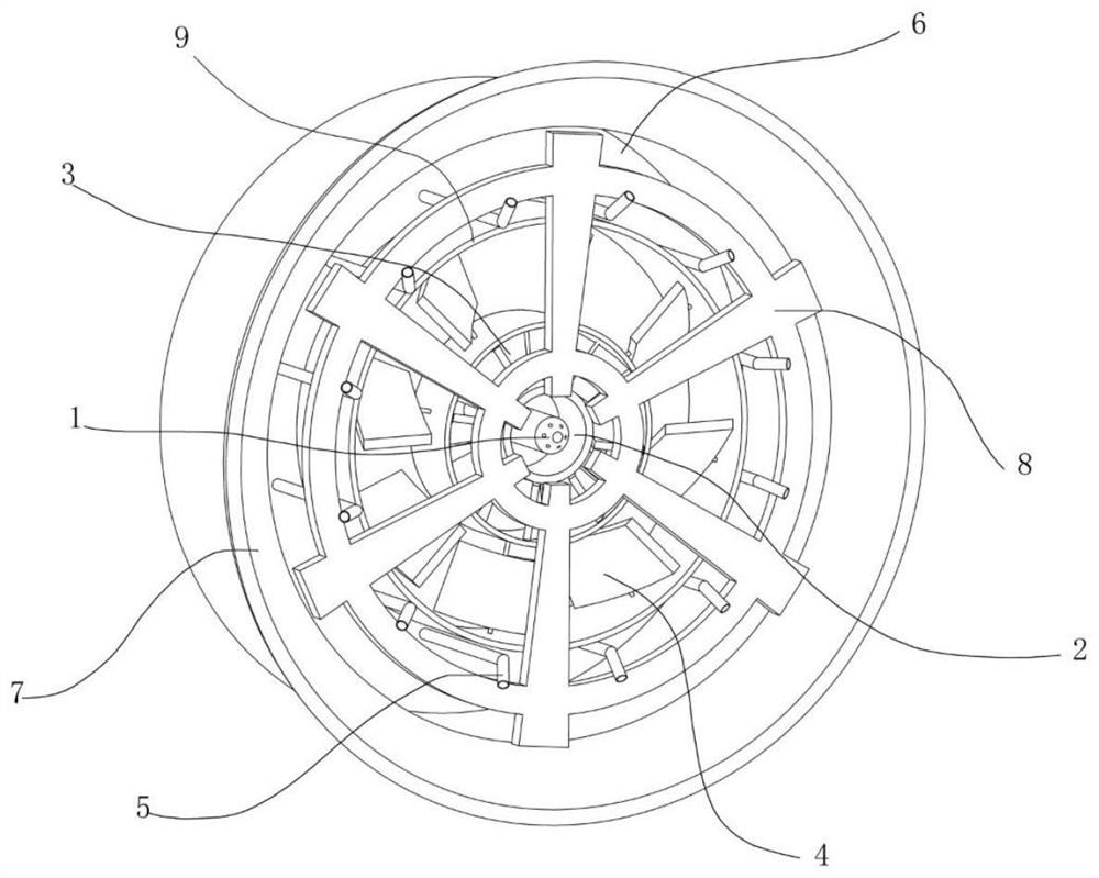
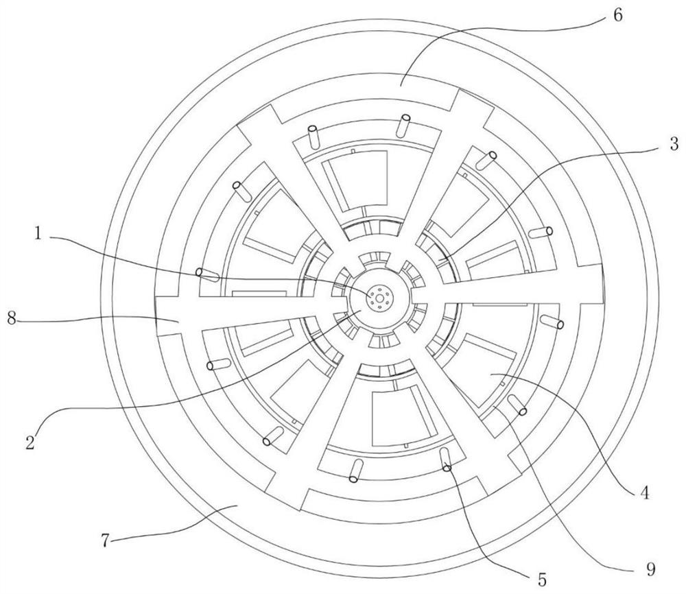
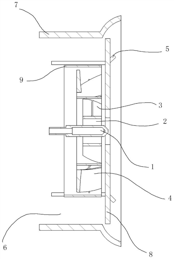
[0030] Structural reference for staged burner of the present invention Figure 1 to Figure 5 , including an outer air cylinder 7 coaxially arranged, an inner air cylinder 9 and a central gas injection channel 1, wherein the inner air cylinder 9 is fixed inside the outer air cylinder 7 through a connecting rod support. The outer air duct 7 is connected with the cylindrical combustion chamber, and its front end can adopt a gradually expanding channel to promote the mixing and full combustion of the gas on the inner peripheral surface of the outer air duct.

[0031] A direct air passage 6 is forme...


PUM


Abstract

An ammonia low-nitrogen multi-stage swirl burner, including an outer air cylinder and an inner air cylinder, a direct air passage is formed between the inner wall of the outer air cylinder and the outer wall of the inner air cylinder, and a number of main gas pipelines are evenly distributed along the outer wall of the inner air cylinder , the inner air duct is coaxial swirl air channel, swirl air channel, central air channel and central gas injection channel from outside to inside. The central gas injection channel, swirl air channel and main gas pipeline divide the gas into three parts; the central air The air is divided into three parts by the channel, the straight air channel and the swirling air channel. The fuel and air are classified in the inner air duct. In addition, the burner can also include a flame dividing ring placed at the front end, which can divide the flame. Increase the contact area between gas and air to make the combustion more complete, and the fuel and air are mixed in layers, which is beneficial to enhance the mixing effect of gas and air. Slowing down the heat radiation transfer between the components and the surrounding high-temperature environment is conducive to improving the service life of the components.

Description

technical field [0001] The invention belongs to the technical field of thermal energy engineering, and relates to a burner, in particular to an ammonia-low-nitrogen multi-stage swirl burner. Background technique [0002] "Hydrogen" energy is considered to be an important direction for the development of the global energy structure in the future, but due to the problems of large-scale production, storage and transportation of hydrogen, ammonia is called "another kind of hydrogen" and is a good hydrogen The carrier and hydrogen storage medium have the advantage of being carbon-free, and the emissions after complete combustion are only water and nitrogen. However, there is an obvious problem with using ammonia as fuel, that is, ammonia contains a lot of nitrogen. When burning with the existing general burner, more nitrogen oxides will inevitably be produced, thereby causing adverse effects on the environment. Therefore, it is necessary to design an excellent burner structure ...

Claims


Application Information

Patent Timeline
Patent Type & Authority Patents(China)
IPC IPC(8): F23D14/24F23D14/46F23D14/62F23D14/70F23D14/84F23C3/00F23C9/06F23N3/00
CPCF23D14/24F23D14/62F23D14/70F23N3/007F23C9/06F23C3/006F23D14/46F23D14/84F23D2203/007
Inventor 张猛郭威吴诗怡李中渊任晋辉董妍苏利天王金华
Owner XI AN JIAOTONG UNIV
Why Eureka
Try Eureka