Surface defect developing device and surface defect detecting equipment

A defect detection and defect technology, which is applied in the direction of measuring devices, optical testing defects/defects, instruments, etc., can solve the problems of entering the camera, increasing the width of the light source, and unsatisfactory defect detection rate, so as to improve work efficiency and improve The effect of the detection rate

Active Publication Date: 2021-06-15
厦门威芯泰科技有限公司
View PDF8 Cites 1 Cited by
  • Summary
  • Abstract
  • Description
  • Claims
  • Application Information

AI Technical Summary

Problems solved by technology

However, at this time, the intensity of reflected light collected by the camera theoretically only accounts for a quarter of the intensity of emitted light, so it is difficult to make the change curve of the gray value of the modulated light in the direction of light and dark changes have a sufficient slope, so defect detection Yield is not satisfactory
When the camera and the stripe light source are arranged on both sides of the normal line, it also encounters great difficulties. Because the four sides of the glass cover of the mobile phone have curvature, the width of the stripe light source must be larger than the width of the glass cover of the mobile phone to make reflection Light enters the camera, and if the light source is far away

Method used


Image

  • Surface defect developing device and surface defect detecting equipment
  • Surface defect developing device and surface defect detecting equipment
  • Surface defect developing device and surface defect detecting equipment

Examples


Embodiment Construction

[0032] In the claims and description, unless otherwise defined, terms such as "first", "second" or "third" are used to distinguish different objects, rather than to describe a specific sequence.

[0033] In the claims and specification, unless otherwise defined, the terms "central", "transverse", "longitudinal", "horizontal", "vertical", "top", "bottom", "inner", "outer", " The orientation or positional relationship indicated by "Up", "Down", "Front", "Back", "Left", "Right", "Clockwise", "Counterclockwise" etc. are based on the orientation and positional relationship shown in the drawings , and are only for the convenience of simplifying the description, and do not imply that the referred device or element must have a specific orientation or be constructed and operated in a specific orientation.

[0034] In the claims and description, unless otherwise defined, the term "fixed connection" or "fixed connection" should be understood in a broad sense, that is, any connection meth...


PUM


Abstract

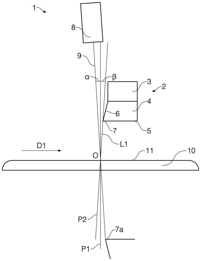
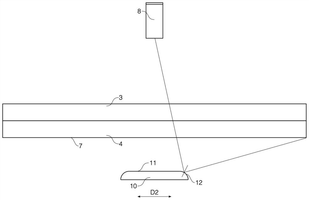
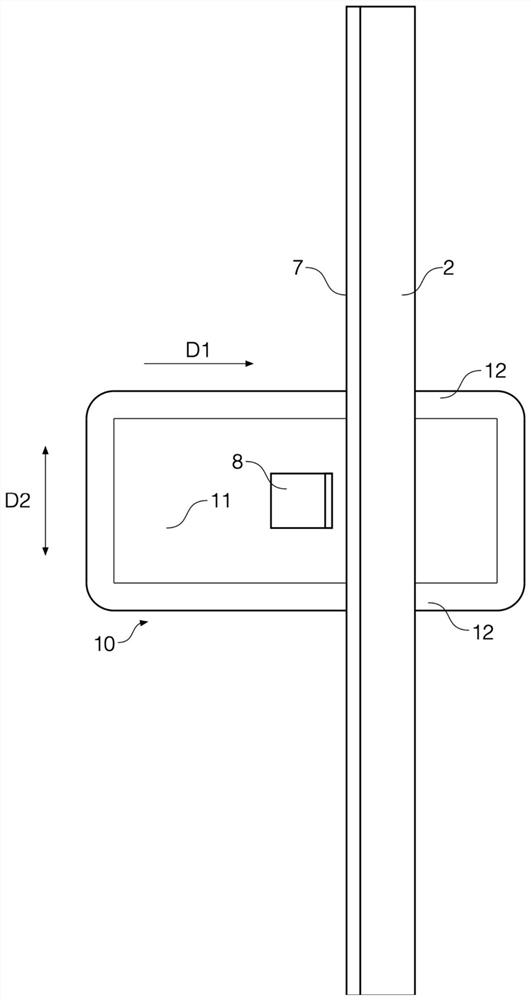
The invention discloses a surface defect developing device and surface defect detecting equipment. The surface defect developing device comprises a light source and a camera, the light source is provided with a folded edge perpendicular to the moving direction of a to-be-detected object, the optical axis of the camera perpendicularly intersects with a virtual image of the folded edge and intersects with the first surface of the to-be-detected object at a first point, a first plane passes through the first point and is perpendicular to the moving direction of the to-be-detected object, and a second plane passes through the first point and the folded edge. The first included angle between the optical axis and the first plane is equal to the second included angle between the vertical line from the first point to the folded edge and the first plane, and any part of the light source is not located in the area between the first plane and the second plane. A surface defect detection device in the surface defect detection equipment synthesizes images continuously shot by the camera into a synthetic image, and judges that a to-be-detected surface has defects when identifying that the change of a gray value in a to-be-detected surface area in the synthetic image exceeds a threshold value. According to the scheme, the influence of interference reflected light on the modulation effect can be avoided under the condition that the light source is close to the surface of the to-be-detected object.

Description

technical field [0001] The application relates to the field of surface defect detection, in particular to a surface defect imaging device and surface defect detection equipment. Background technique [0002] In the prior art, the modulated light is used to irradiate the surface of an object by using a striped light source, and the reflected light is collected by a camera to find surface defects in the modulated area (light and dark change area). When this technology is applied to detect surface defects of glass, especially the surface defects of mobile phone glass covers with curved surfaces, great difficulties arise. Generally, a semi-reflective and semi-transparent glass with an inclination angle of 45° is used, the camera is arranged in the normal direction, the stripe light source is arranged in the direction perpendicular to the normal, and the modulated light is formed by reflecting the stripe light source through the semi-reflective and semi-transparent glass, and the...

Claims


Application Information

Patent Timeline
IPC IPC(8): G01N21/88G01N21/01
CPCG01N21/8806G01N21/01
Inventor 王磊
Owner 厦门威芯泰科技有限公司
Why Eureka
Try Eureka