Red light LED chip, preparation method and display panel

A technology of LED chips and red light, which is applied in nanotechnology, electrical components, nanotechnology, etc. for materials and surface science, and can solve problems that affect the uniformity of light emitted by red LED chips and poor hole dispersion

Pending Publication Date: 2021-06-15
CHONGQING KONKA PHOTOELECTRIC TECH RES INST CO LTD
View PDF11 Cites 0 Cited by
  • Summary
  • Abstract
  • Description
  • Claims
  • Application Information

AI Technical Summary

Problems solved by technology

[0004] In view of the deficiencies in the above-mentioned related technologies, the purpose of this application is to provide a red light LED chip and its preparation method and display panel, aiming to solve the problem of poor hole dispersion effect caused by the use of ITO layer in the related technology, which affects the red light. The problem of uniformity of light output from LED chips

Method used


Image

  • Red light LED chip, preparation method and display panel
  • Red light LED chip, preparation method and display panel
  • Red light LED chip, preparation method and display panel

Examples


Embodiment Construction

[0048] In order to facilitate the understanding of the present application, the present application will be described more fully below with reference to the relevant drawings. Preferred embodiments of the application are shown in the accompanying drawings. However, the present application can be embodied in many different forms and is not limited to the embodiments described herein. On the contrary, the purpose of providing these embodiments is to make the disclosure of the application more thorough and comprehensive.

[0049]Unless otherwise defined, all technical and scientific terms used herein have the same meaning as commonly understood by one of ordinary skill in the technical field to which this application belongs. The terminology used herein in the description of the application is only for the purpose of describing specific embodiments, and is not intended to limit the application.

[0050] In the related art, ITO is used as the hole dispersing layer, but as a semi...


PUM

PropertyMeasurementUnit
wavelengthaaaaaaaaaa

Abstract

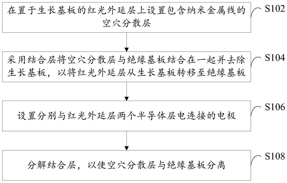
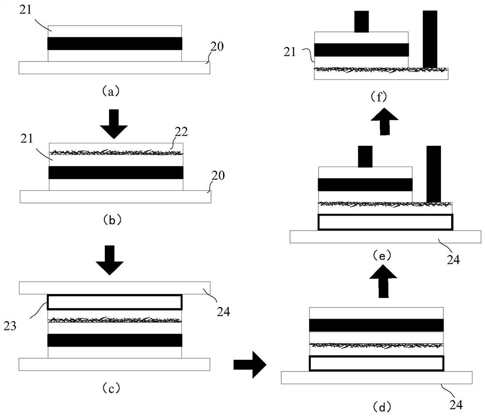
The invention relates to a red light LED chip, a preparation method and a display panel. When the red light LED chip is prepared, a hole dispersion layer is formed by adopting an adhesive dispersed with nano metal wires, and the nano metal wires are at least uniformly distributed on one side, close to a red light epitaxial layer, of the hole dispersion layer, so that holes are uniformly dispersed on the whole surface of the red light epitaxial layer; and by using the excellent conductivity of the metal nanowires, electrons at an electrode are dispersed, electron aggregation is reduced, the electrons / holes are uniformly distributed all over the light-emitting surface of the red light epitaxial layer, and the light-emitting effect of the red light epitaxial layer is improved.

Description

technical field [0001] The technical field of LED of the present invention particularly relates to a red light LED chip, a preparation method, and a display panel. Background technique [0002] Due to the material of the epitaxial layer of the red LED chip, an ITO (indium tin oxide) layer must be placed on the P-type semiconductor layer, otherwise electrons will directly pass through the active layer from the P electrode to the N-type semiconductor layer by the shortest path At the N electrode on the top, resulting in uneven light output from the red LED chip. The ITO layer mainly plays a role of hole transport and hole dispersion in the red LED chip, and is used to disperse holes to the entire surface of the P-type semiconductor layer. But in fact, as a semiconductor material, ITO has an unsatisfactory hole dispersion effect, which in turn leads to the problem of poor light extraction effect of the red LED chip. [0003] Therefore, how to improve the effect of dispersing ...

Claims


Application Information

Patent Timeline
Patent Type & Authority Applications(China)
IPC IPC(8): H01L33/00H01L33/14B82Y30/00B82Y40/00
CPCH01L33/0075H01L33/14B82Y30/00B82Y40/00
Inventor 翟峰唐彪
Owner CHONGQING KONKA PHOTOELECTRIC TECH RES INST CO LTD
Why Eureka
Try Eureka