Rotor assembly and self-starting permanent magnet synchronous reluctance motor
A rotor and component technology, which is applied to synchronous machine parts, electric components, magnetic circuit rotating parts, etc., can solve the problems of reduced motor efficiency, reduced motor system efficiency, and high cost, and achieves the goal of improving motor efficiency and utilization efficiency. Effect
- Summary
- Abstract
- Description
- Claims
- Application Information
AI Technical Summary
Problems solved by technology
Method used
Image


Examples
Embodiment Construction
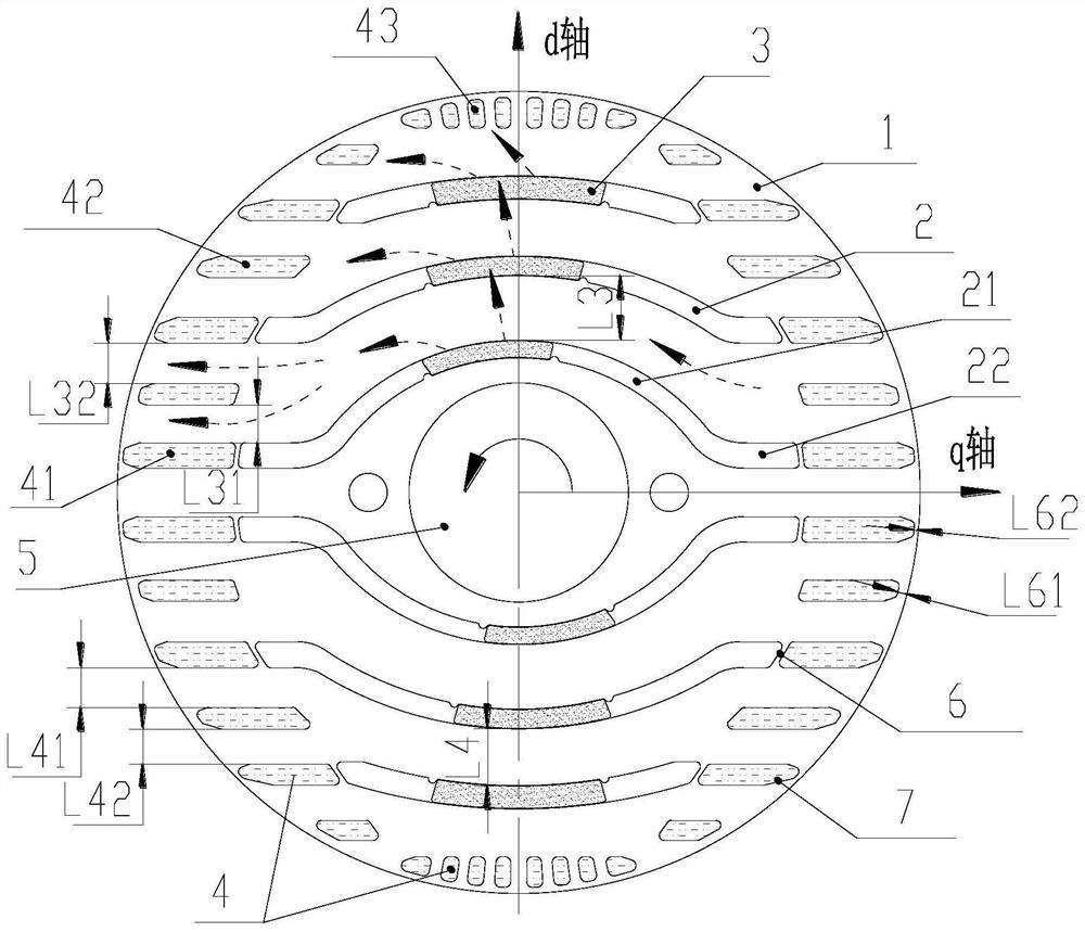
[0036] see in conjunction Figure 1 to Figure 7 As shown, according to the embodiment of the present application, the rotor assembly includes a rotor core 1. On the cross section of the rotor core 1, the rotor core 1 is provided with a shaft hole 5, a slot slot 2, a q-axis squirrel cage slot 41 and The permanent magnet 3, the q-axis squirrel cage groove 41 is arranged at both ends of the slit groove 2, the permanent magnet 3 is arranged in the slit groove 2, at least the permanent magnet 3 located in the innermost layer along the d-axis direction is asymmetrical with respect to the d-axis Arranged, and the offset direction of the permanent magnet 3 located in the innermost layer relative to the d-axis is consistent with the rotation direction of the rotor assembly.
[0037] This structure can make the magnetic flux generated by the offset permanent magnet flow more towards the direction of the q-axis magnetic flux of the rotor, provide more q-axis magnets, and avoid the perman...
PUM
 Abstract
Description
Claims
Application Information