Drawing machine mold core replacement device and using method thereof
What is AI technical title?
AI technical title is built by Patsnap AI team. It summarizes the technical point description of the patent document.
A technology of drawing machine and mold core, which is applied in the direction of wire drawing die, etc., and can solve the problems of disassembly and assembly of mold core
Active Publication Date: 2021-11-23
WUXI NEWAY STEEL
View PDF0 Cites 0 Cited by
Summary
Abstract
Description
Claims
Application Information
AI Technical Summary
This helps you quickly interpret patents by identifying the three key elements:
Problems solved by technology
Method used
Benefits of technology
Problems solved by technology
[0006] In order to improve the problem that the mold core needs to be frequently disassembled and assembled when replacing the mold core, the application provides a drawing machine mold core replacement device and its use method
Method used
Image
Click on the blue label to locate the original text in one second.
Reading with bidirectional positioning of images and text.
Examples
Embodiment 1
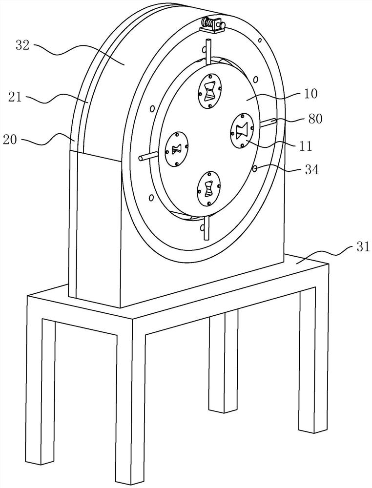
[0044] refer to figure 1 The device for replacing the core 11 of the drawing machine includes a support assembly, an installation assembly rotatably connected to the support assembly, an adjustment assembly for adjusting the rotation angle of the installation assembly, and a locking assembly for locking the support assembly and the installation assembly.
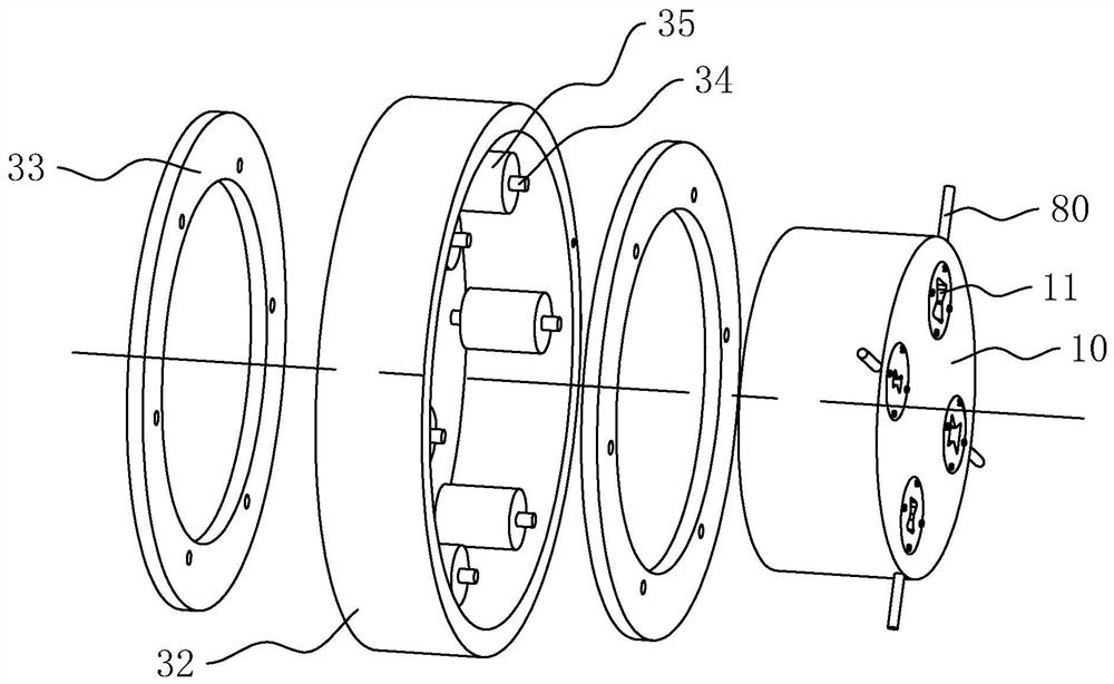
[0045] refer to figure 1 and figure 2 , the support assembly includes a support platform 31 , a support ring 32 , a bearing ring 33 , a bearing rod 34 , and a sleeve 35 . The support platform 31 is placed on the ground, the support ring 32 is ring-shaped and the axis is horizontally arranged, and the bottom of the support ring 32 is welded on the support platform 31 .
[0046] refer to figure 2 , the bearing ring 33 is located at the two ends of the inner wall of the support ring 32, and one is fixedly connected respectively, the bearing ring 33 and the support ring 32 are arranged coaxially, there is a distance between...
Embodiment 2
[0078] refer to figure 1 , a method for using a drawing machine mold core 11 replacement device, its use steps are as follows:
[0079] S1, plate loading: several mold cores 11 are circumferentially bolted to the mounting plate 10 according to the sequence of use;
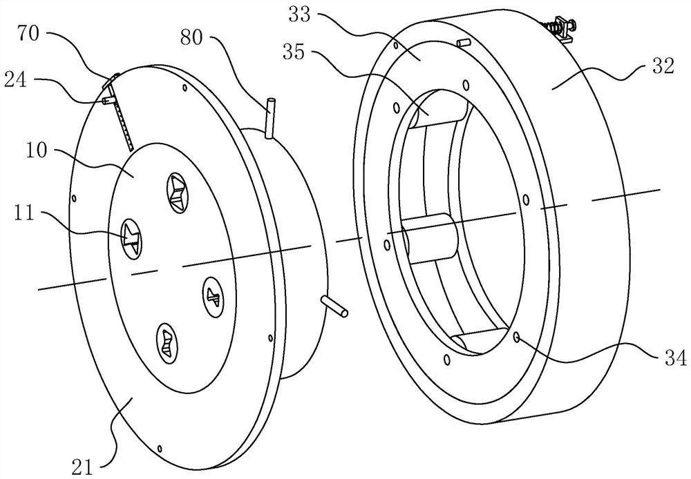
[0080] refer to Figure 5 , S2, position adjustment: the operator manually adjusts the offset lever 24 to the connection between the maximum deflection groove 201 and the reset groove 203, and makes the offset lever 24 touch the side wall at the end of the maximum deflection groove 201, and through the insertion rod The end of 63 is inserted into the corresponding insertion hole 212 to lock the mounting plate 10 tightly.
[0081] refer to Figure 5 and Figure 6 , S3, deflection: when replacing the mold core 11, the operator pulls the insertion rod 63 out of the insertion hole 212, and then rotates the mounting plate 10, the deflection rod 24 moves along the arc direction of the deflection groove 201, and passe...
PUM
Abstract
This application relates to the field of drawing machines, in particular to a drawing machine mold core replacement device and its use method, which includes a support assembly and a mounting assembly rotatably connected to the support assembly, the mounting assembly includes a As for the mounting plate, several mold cores are pierced between the two side walls in the axial direction of the mounting plate, the axes of the cores are parallel to the axis of the mounting plate, and the several mold cores are arranged circumferentially around the axis of the mounting plate. The application has the advantages of reducing the possibility of operators frequently disassembling and assembling mold cores, and also has the advantages of energy saving and environmental protection.
Description
technical field [0001] The present application relates to the field of drawing machines, in particular to a drawing machine mold core replacement device and a method for using the same. Background technique [0002] The drawing machine is an industrial equipment composed of mechanical equipment, lubrication equipment, electrical equipment, hydraulic and pneumatic systems, etc. It is a device for drawing metal bars. According to different structures, the drawing machine can be divided into chain drawing machine, hydraulic drawing machine, reel drawing machine. [0003] The chain drawing machine in the related art comprises a mold base and a mold core detachably connected to the mold base. The mold core is provided with a deformation groove along its axial direction, and the shape and size of the deformation groove section on different mold cores are different. Not the same. [0004] When drawing, the operator passes one end of the metal bar through the deformation groove of...
Claims
Application Information
Patent Timeline
Application Date:The date an application was filed.
Publication Date:The date a patent or application was officially published.
First Publication Date:The earliest publication date of a patent with the same application number.
Issue Date:Publication date of the patent grant document.
PCT Entry Date:The Entry date of PCT National Phase.
Estimated Expiry Date:The statutory expiry date of a patent right according to the Patent Law, and it is the longest term of protection that the patent right can achieve without the termination of the patent right due to other reasons(Term extension factor has been taken into account ).
Invalid Date:Actual expiry date is based on effective date or publication date of legal transaction data of invalid patent.

