
Assembly machine for retainer ring and screw of shield assembly of cutting and grinding machine

A technology for assembling machines and shields, which is applied to conveyor objects, transportation and packaging, and metal processing. It can solve problems such as poor reliability, unstable quality, and low production efficiency, and achieve product quality improvement, production efficiency improvement, and savings. Effects of assembly operations

Pending Publication Date: 2021-06-18
成都华川电装有限责任公司
View PDF0 Cites 0 Cited by
  • Summary
  • Abstract
  • Description
  • Claims
  • Application Information

AI Technical Summary

Problems solved by technology

[0003] There are deficiencies: manual visual inspection of whether the screw 3 is assembled in place is poor in reliability, and the quality is unstable; manually place the shield 1 to position and press it, manually take and place the collar 2 to fix it, manually take and place the screw 3, and manually start the electric screwdriver to screw in the screw 3. Visually check whether the screws are assembled in place, loosen the positioning tool, and take the product. The production cycle is 30-35 seconds / piece, and the production efficiency is low.

Method used


Image

  • Assembly machine for retainer ring and screw of shield assembly of cutting and grinding machine
  • Assembly machine for retainer ring and screw of shield assembly of cutting and grinding machine
  • Assembly machine for retainer ring and screw of shield assembly of cutting and grinding machine

Examples


Embodiment Construction

[0023] Combine below Figure 1 to Figure 7 The present invention will be described.

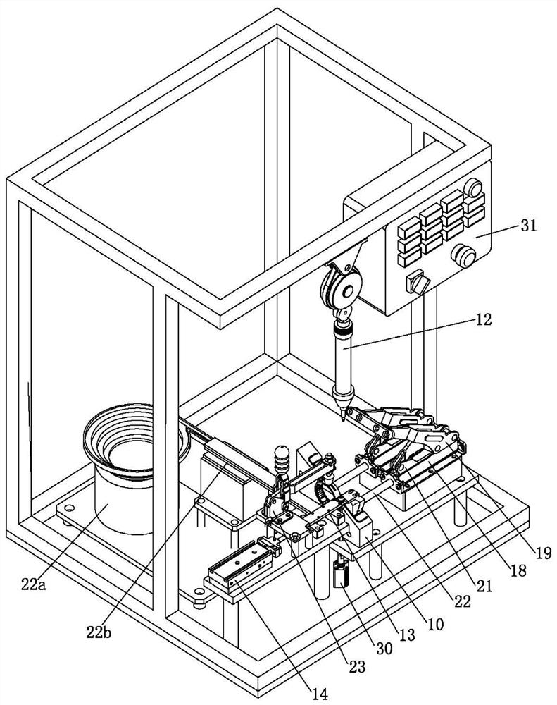
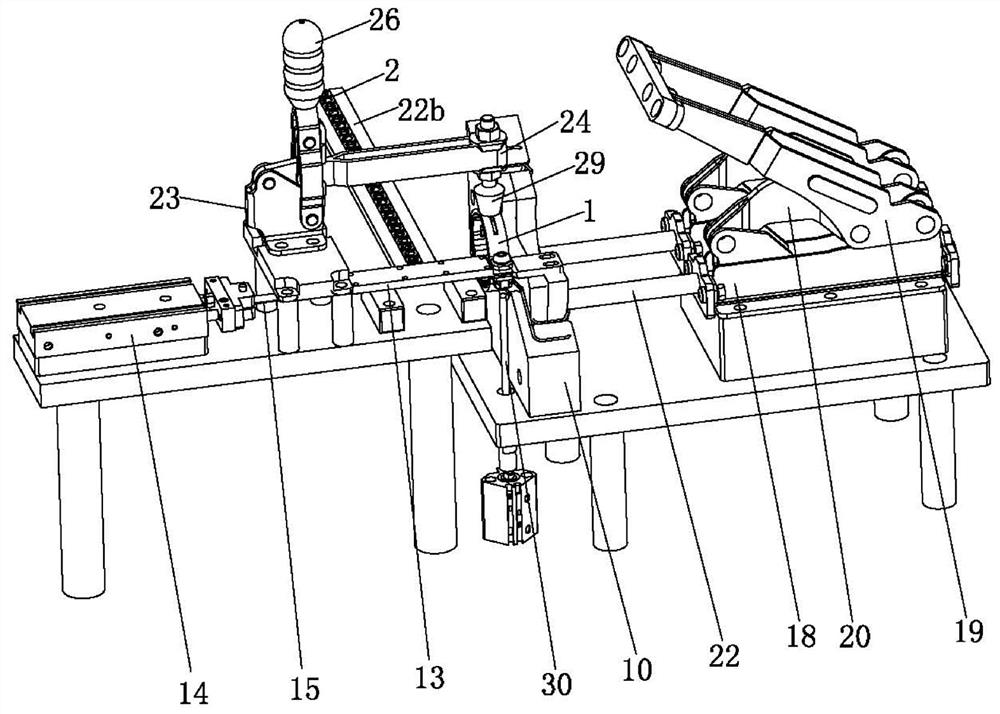
[0024] The assembly machine for the collar and the screw of the shield assembly of the cutting mill of the present invention includes an assembly seat 10 cooperating with the shield 1, an electric screwdriver 12, a pushing mechanism, a first positioning mechanism, a bearing seat 11, a detection mechanism, a control The following is a detailed description of each part and the relationship between them:

[0025] The fitting seat 10 is provided with a matching groove 10a, and the fitting seat 10 forms a supporting effect on the shield 1 after the shield 1 is matched with the fitting groove 10a. The shape of the fitting groove 10a matches the shape of the shield 1, therefore, the fitting groove 10a is an open groove instead of an annular groove.

[0026] The pushing mechanism pushes the received collar 2 to a position where it is assembled with the screw 3 , that is, pushes the collar 2 onto th...


PUM


Abstract

The invention discloses an assembling machine for a retainer ring and a screw of a shield assembly of a cutting and grinding machine. The assembly machine comprises an assembly seat matched with a shield and an electric screw driver, and further comprises a pushing mechanism for pushing the received retainer ring to a position where the retainer ring and the screw are assembled, and the pushing mechanism is positioned on one side of the assembly seat; the assembly machine further comprises a first positioning mechanism used for applying axial pressing force to the shield matched on the assembly seat and positioned on the other side of the assembly seat, a bearing seat, a detection mechanism, and a controller; the bearing seat is used for bearing a clamping ring output by the pushing mechanism, a through hole allowing the screw to penetrate through is formed in the bearing seat, a receding opening used for being separated from the screw is further formed in the circumferential surface of the bearing seat, and the bearing seat is connected with the pushing mechanism or the first positioning mechanism; the detection mechanism is used for detecting whether the screw is screwed in place or not; and the controller is electrically connected with the electric screw driver and the detection mechanism, and when the controller receives a signal which is provided by the detection mechanism and indicates that the screw is screwed in place, the controller controls the electric screw driver to stop working. The assembling efficiency can be improved.

Description

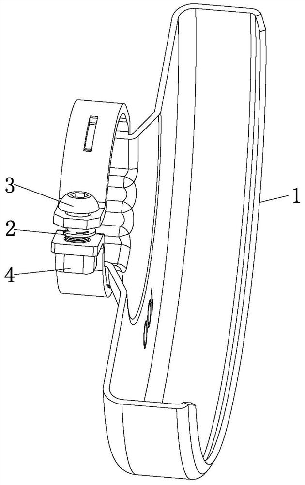
technical field [0001] The invention relates to an assembling machine, in particular to an assembling machine for collars and screws of a cutter-mill shield assembly. Background technique [0002] Such as figure 1 , the cutting mill shield assembly needs to assemble the collar 2 and the screw 3 on the shield 1 according to the requirements. The current process is: first, the operator manually places the shield 1 on the positioning tool for positioning and pressing, and then the collar 2 Put it on the hole where the shield 1 is to be assembled, then hold the screw 3 and place it at the hole of the shield 1, and then start the electric screwdriver to rotate the screw 3 through the collar and screw it into the nut 4 on the shield 1 , Visually check that the end face of the screw 3 is flush with the nut 4 on the shield 1, stop the electric screwdriver, and finally loosen the positioning tool, take out the assembled components and put them into the container. [0003] There are...

Claims


Application Information

Patent Timeline
Patent Type & Authority Applications(China)
IPC IPC(8): B23P19/06B23P19/00B65G47/14
CPCB23P19/001B23P19/06B65G47/1421
Inventor 周行建刘博文张兵林军李开强
Owner 成都华川电装有限责任公司
Learn More