High-frequency quenching machine for shaft parts

A technology for high-frequency quenching and shaft parts, applied in the field of parts processing, can solve the problems of inability to guarantee the safety of workers, high labor intensity of workers, etc., to reduce the possibility of scalding the operator's hand, reduce the possibility of taking workpieces, and improve stability. sexual effect

Inactive Publication Date: 2022-07-12
烟台隆辉金属制品有限公司
View PDF6 Cites 0 Cited by
  • Summary
  • Abstract
  • Description
  • Claims
  • Application Information

AI Technical Summary

Problems solved by technology

[0003] For the quenching treatment of shaft parts, the existing heat treatment factories usually use simple heat treatment equipment, by setting two thimbles to fix the shaft, and then heat treatment it by high-frequency coils. After that, it is usually necessary to manually remove the workpiece, which cannot guarantee the safety of workers

Method used


Image

  • High-frequency quenching machine for shaft parts
  • High-frequency quenching machine for shaft parts
  • High-frequency quenching machine for shaft parts

Examples


Embodiment 1

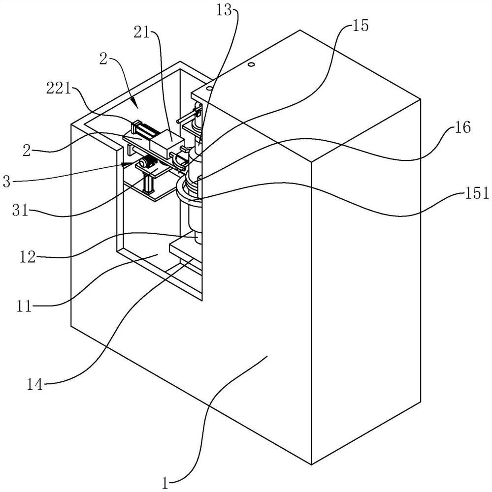
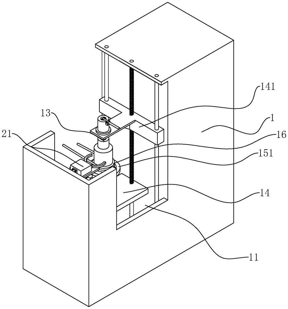
[0035] refer to figure 1 and figure 2 , a high-frequency quenching machine for shaft parts, including a body 1, the body 1 is provided with a cooling pool 11, the cooling pool 11 is filled with cooling liquid, so as to cool the workpiece after processing, the body 1 is provided with a sliding table 14 , the sliding table 14 is slidably connected with the body 1 in the vertical direction, the sliding table 14 is located in the cooling pool 11, and the cooling purpose of the workpiece can be achieved by sliding the sliding table 14 into the cooling pool 11, and the body 1 is provided with a first fixed shaft 12 and The second fixed shaft 13, the first fixed shaft 12 is located on the upper end surface of the sliding table 14, and the first fixed shaft 12 is fixedly connected with the sliding table 14, the body 1 is provided with a linkage block 141, and the second fixed shaft 13 is connected with the linkage block 141 , and the linkage block 141 and the sliding table 14 are co...

Embodiment 2

[0045] The main difference between Embodiment 2 and Embodiment 1 is that the driving manner of the worm 33 is different.

[0046] refer to Figure 5 , the support plate 31 is provided with a hand wheel 4, the hand wheel 4 is arranged vertically, the rotating shaft of the hand wheel 4 is fixedly connected to the worm 33 coaxially, when the workpiece needs to be taken, the operator turns the hand wheel 4, and when the hand wheel 4 rotates, The worm 33 can be driven to rotate, and the rotation of the worm 33 drives the worm wheel 32 to rotate, so as to realize the purpose of driving the installation table 2 to rotate, so as to facilitate the operator to take the workpiece and improve the convenience for the operator to take the workpiece.

[0047] refer to Figure 5 , the outer wall of the handwheel 4 is provided with an anti-scalding sleeve 41 , and the anti-scalding sleeve 41 is fixedly connected with the handwheel 4 . When the operator rotates the handwheel 4 , the anti-scal...


PUM


Abstract

The invention discloses a shaft part high-frequency quenching machine, and relates to the field of part machining, the shaft part high-frequency quenching machine comprises a machine body, the machine body is provided with a sliding table and a cooling pool, the sliding table is located in the cooling pool, the sliding table is slidably connected with the machine body in the vertical direction, and the upper end face of the sliding table is provided with a first fixing shaft; the machine body is provided with a sliding table, the sliding table is connected with a linkage block, the linkage block is provided with a second fixing shaft, the first fixing shaft and the second fixing shaft are located on the same vertical line, the sliding table is provided with an electric heating wire, the machine body is provided with a clamping jaw, the clamping jaw is located between the first fixing shaft and the second fixing shaft, and the clamping jaw is in sliding connection with the machine body in the horizontal direction. The machine body is provided with a driving mechanism used for driving the clamping jaws to slide. The manual labor intensity can be reduced, and the safety of workers is guaranteed.

Description

technical field [0001] The invention relates to the technical field of parts processing, in particular to a high-frequency quenching machine for shaft parts. Background technique [0002] The quenching process is widely used in the modern machinery manufacturing industry. Important parts in machinery, especially steel parts used in automobiles, airplanes, and rockets, are almost all quenched. In order to meet the different technical requirements of various parts, various quenching processes have been developed, such as surface quenching, overall quenching, and local quenching. [0003] For the quenching treatment of shaft parts, the existing heat treatment plants usually use simple heat treatment equipment. The shaft is fixed by setting two thimbles, and then heat treatment is performed by a high-frequency coil. This method is labor-intensive and the quenching is completed. After that, the workpiece usually needs to be removed manually, which cannot guarantee the safety of...

Claims


Application Information

Patent Timeline
Patent Type & Authority Applications(China)
IPC IPC(8): C21D9/28C21D1/63C21D1/42C21D1/10
CPCC21D9/28C21D1/63C21D1/42C21D1/10Y02P10/25
Inventor 孙成献苗德权孙振跃
Owner 烟台隆辉金属制品有限公司
Why Eureka
Try Eureka