
Multifunctional solution stirring device

A stirring device, multi-functional technology, applied in the field of solution stirring device, can solve the problems of increased accidents due to transfer back and forth, unsuitable for teaching units, and affecting experimental efficiency, etc., to achieve smooth experimental process, simple and easy cleaning, and accurate experimental data Effect

Active Publication Date: 2020-01-31
重庆万盛川东化工有限公司
View PDF15 Cites 0 Cited by
  • Summary
  • Abstract
  • Description
  • Claims
  • Application Information

AI Technical Summary

Problems solved by technology

Generally speaking, the experimental equipment equipped in the laboratory of the teaching unit is relatively simple. During the experiment, routine operations such as stirring and mixing the reaction solution, heating the reaction solution, and weighing and measuring the solution and pharmaceuticals all need the help of a separate The instruments are carried out sequentially. On the one hand, it affects the efficiency of the experiment. On the other hand, the transfer of experimental instruments, containers, solutions, pharmaceuticals and other items increases the probability of accidents.
In the prior art, there is also an all-in-one experimental instrument with comprehensive functions, which generally needs to be equipped with a special experimental container for work, and cannot work stably with the beaker generally configured in the laboratory, and needs to be purchased in a complete set, with high operating costs. The operation technology has high requirements. This kind of experimental equipment is mostly used in professional scientific research laboratories, and is not suitable for demonstration routine experiments in teaching units.

Method used


Image

  • Multifunctional solution stirring device
  • Multifunctional solution stirring device
  • Multifunctional solution stirring device

Examples


Embodiment Construction

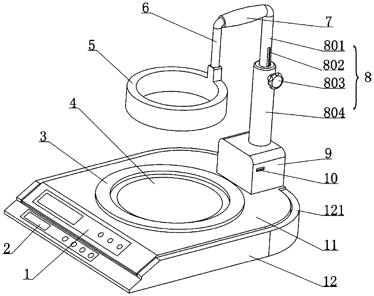
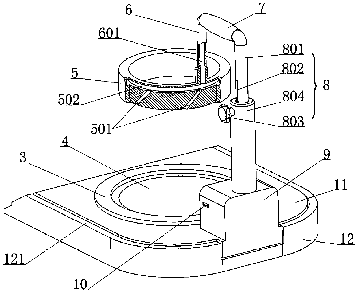
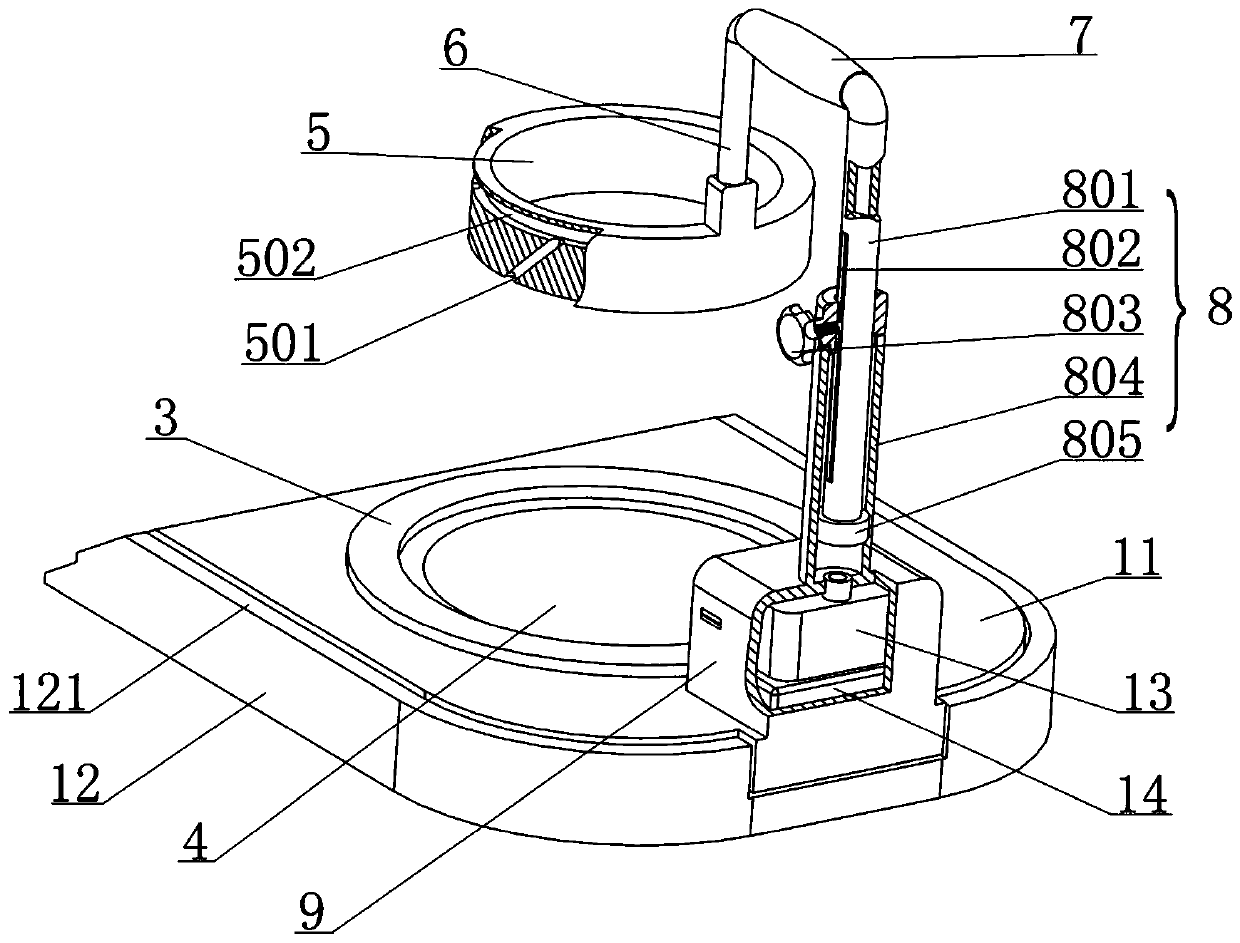
[0017] With reference to 1-5, the present invention discloses a multifunctional solution stirring device, which includes a bearing platform 11 and a micro platform scale 12. The bearing platform 11 is provided with a telescopic rod 8, an air pump 13, a controller, and a limiter. The ring 3, the electric heating device 4 and the battery 14; the limiting ring 3 has a ring shape, which protrudes from the upper surface of the bearing platform 11, the inner ring diameter is slightly larger than the outer diameter of the bottom of the beaker 15, which is used to limit the beaker 15 The electric heating device 4 is installed on the carrying platform 11 and is located in the limit ring 3, which is used to heat the bottom of the beaker 15 and indirectly heat the solution in the beaker 15. In the prior art, the electric heating device 4 It can be implemented with a resistance heating plate or an electromagnetic heating device, both of which can achieve its function in the present inventio...


PUM


Abstract

The invention relates to experimental equipment, and particularly discloses a multifunctional solution stirring device which is characterized in that a telescopic rod, an air pump, a controller, a limiting ring and an electric heating device are arranged on a bearing table; a stirring ring is supported on the telescopic rod through a crank arm, an annular cavity and an inclined hole are formed inthe stirring ring, and when the air pump works, the inclined hole can blow air to the liquid level in a beaker to drive a solution to rotate; the bearing table is arranged on a miniature platform scale, and the miniature platform scale can meter the weight of an object on the miniature platform scale and the weight change of the object. The multifunctional solution stirring device integrates the functions of stirring, heating and weighing, various common operation requirements in the experiment process can be met, the stirring ring is left in the beaker, operation on the solution is not affected, the experiment process is smoother and more efficient, and the accident rate caused by taking and replacing experiment instruments can be effectively reduced; the stirring device is simple in structure, low in acquisition cost and beneficial to popularization and application, and has a wide application prospect.

Description

Technical field [0001] The invention relates to an experimental equipment, in particular to a solution stirring device. Background technique [0002] In the scientific research and teaching of physics, biology, especially chemistry, experiment is one of the indispensable items, and the experiment process needs to be completed with the cooperation of special experimental equipment. Generally speaking, the experimental equipment equipped in the laboratory of the teaching unit is relatively simple. During the experiment, the routine operations such as stirring and mixing the reaction solution, heating the reaction solution, weighing the solution and the medicine, etc. all need to rely on a separate The equipment is carried out in sequence, on the one hand, it affects the efficiency of the experiment, on the other hand, the back and forth transfer of experimental equipment, containers, solutions, medicines and other items increases the probability of accidents. In the prior art, the...

Claims


Application Information

Patent Timeline
Patent Type & Authority Applications(China)
IPC IPC(8): B01F13/02B01F15/00B01F15/06B01F33/40
CPCB01F33/409B01F35/2117B01F35/94B01F35/92B01F2101/23B01F2035/99
Inventor 宋明奎
Owner 重庆万盛川东化工有限公司
Learn More