Electric vehicle chassis charging and battery replacing station and battery replacing method
A charging and swapping station and electric vehicle technology, applied in the field of swapping stations, can solve the problems of low efficiency and precision, and achieve good positioning effect, convenient movement, and convenient driving of wheels
- Summary
- Abstract
- Description
- Claims
- Application Information
AI Technical Summary
Problems solved by technology
Method used
Image

Examples
Embodiment 1
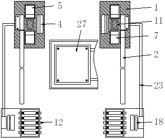
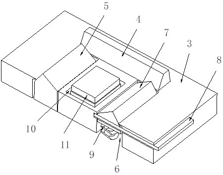
[0032] see Figure 1-6 , a charging and replacing station for an electric vehicle chassis and a method for replacing batteries, comprising a lifting frame 27 for transporting vehicle batteries and two positioning assemblies 1, the positioning assembly 1 is composed of a guide rod 2 and a fixed base 3, and the fixed base 3 is located at one end of the guide rod 2, and one side of the fixed base 3 is provided with a limit baffle 4, the limit baffle 4 and the guide rod 2 are arranged parallel to each other, and the fixed base 3 is provided with a first guide seat 5 and a fixed groove 6, and the first guide seat 5 and the fixed groove 6 are all located on the side of the limit baffle plate 4 close to the guide rod 2, the second guide seat 7 is movable in the fixed groove 6, and one end of the fixed base 3 is provided for A stopper 8 for limiting the range of motion of the second guide seat 7, a support mechanism 12 is provided at the end of the guide rod 2 away from the fixed base...
Embodiment 2
[0036] see Figure 6 , the technical solution is basically the same as that of Embodiment 1, the only difference being that the limiting member 8 is located at one end of the fixed base 3 close to the first guide seat 5, and one end of the limiting member 8 is provided with two limiting columns, the limiting columns One end passes through the first guide seat 5 and the second guide seat 7 in turn and is plugged into the fixed base 3 .
[0037] Since vehicles are divided into front-drive and rear-drive, in order to be suitable for different vehicles, this technical solution sets up different limiters 8. When the vehicle is rear-drive, the car is directly driven into the battery replacement station when it is in use. At this time, the installation position of the fixed base 3 is upside down with that in Embodiment 1. The front wheel of the car will first pass through the first guide seat 5 and then sink into the limit groove. When the car needs to be driven out, the limit Part ...
Embodiment 3
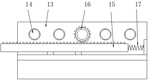
[0039] see figure 2 and 3 , this technical solution is a further improvement on Example 1, the top ends of the first guide seat 5 and the second guide seat 7 are triangular, and there is a first limit between the first guide seat 5 and the second guide seat 7 The positioning slot 10, the first limiting slot 10 is provided with a support plate 11. Guide rod 2 is provided with auxiliary positioning mechanism 18 away from one end of positioning assembly 1, and auxiliary positioning mechanism 18 comprises base 19, movable seat 20 and push pedal 21, and one side of push pedal 21 is provided with inclined-plane, and push pedal 21 passes guide rail and The base 19 is slidably connected up and down, the bottom end of the push plate 21 is elastically connected with the base 19 by the support spring 22, one side of the push plate 21 is provided with a connecting rod 23, and one end of the connecting rod 23 is fixedly connected with the support plate 11, and the movable seat 20 Be pos...
PUM
 Abstract
Description
Claims
Application Information
 - R&D
- Intellectual Property
- Life Sciences
- Materials
- Tech Scout
- Unparalleled Data Quality
- Higher Quality Content
- 60% Fewer Hallucinations
Browse by: Latest US Patents, China's latest patents, Technical Efficacy Thesaurus, Application Domain, Technology Topic, Popular Technical Reports.
© 2025 PatSnap. All rights reserved.Legal|Privacy policy|Modern Slavery Act Transparency Statement|Sitemap|About US| Contact US: help@patsnap.com