Unmanned aerial vehicle panoramic shooting cradle head in limited space

A technology with limited space and gimbal, applied in the field of panoramic shooting of drones, can solve the problems of large size of multi-rotor drones, increasing the number of cameras carried, and shooting blind spots on the rotors, achieving flexible framing, shortening the turning radius, and shooting wide angle effect

Pending Publication Date: 2021-06-18
马丽
View PDF0 Cites 0 Cited by
  • Summary
  • Abstract
  • Description
  • Claims
  • Application Information

AI Technical Summary

Problems solved by technology

[0002] The pan-tilt for panoramic shooting of UAV refers to the UAV as a carrier, and the pan-tilt is used to rotate and shoot the camera in a 360° direction. Most of the existing UAV shooting pan-tilts are placed on the lower side of the UAV body. , when shooting, the gimbal drives the camera to rotate to complete the panoramic shooting. However, due to the impact of the camera's own field of view, it is difficult for a single camera to meet the panoramic shooting, and increasing the number of cameras carried will easily increase the energy consumption of the drone and reduce the cruising range. Experience
[0003] In addition, in order to ensure stable shooting, the shooting platform is mostly installed on multi-rotor drones. However, with the gradual increase in the popularity of drones, in order to cater to the publicity of major scenic spots and shopping malls, drones are often used for publicity shooting. Therefore, UAVs often fly at low altitudes, which is convenient for framing, while multi-rotor UAVs are larger in size, have more rotors and have shooting blind spots, and the battery life is shorter. In a narrow shooting space, the flexibility is low, so it is not suitable for Panoramic shooting, while the dual-rotor UAV can only turn by adjusting the direction of the rotor, the turning radius is too large, it is easy to cause damage to the subject in a small space, and affect the shooting efficiency

Method used


Image

  • Unmanned aerial vehicle panoramic shooting cradle head in limited space
  • Unmanned aerial vehicle panoramic shooting cradle head in limited space
  • Unmanned aerial vehicle panoramic shooting cradle head in limited space

Examples


Embodiment Construction

[0030] The following will clearly and completely describe the technical solutions in the embodiments of the present invention with reference to the accompanying drawings in the embodiments of the present invention. Obviously, the described embodiments are only some, not all, embodiments of the present invention. Based on the embodiments of the present invention, all other embodiments obtained by persons of ordinary skill in the art without making creative efforts belong to the protection scope of the present invention.

[0031] The invention provides technical solutions:

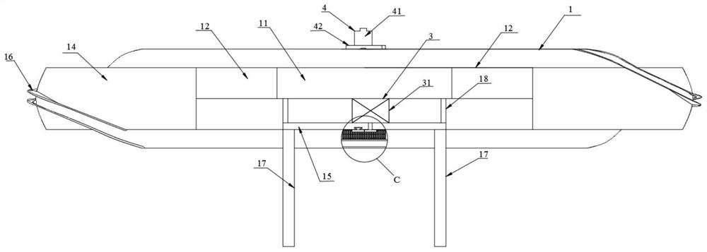
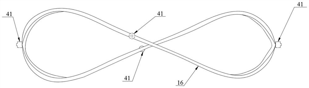
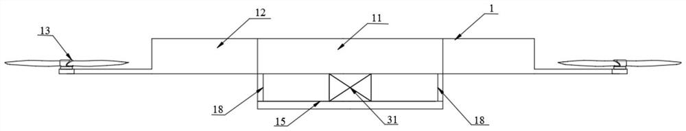
[0032] Such as Figure 1-9 As shown, the UAV panoramic shooting platform in a limited space includes a fuselage assembly 1, a sliding device 2, a power unit 3 and a shooting device 4, the power unit 3 is connected to the fuselage assembly 1, and the fuselage assembly 1 is movably connected to the sliding device 2, the sliding device 2 is movably connected to the power device 3, the shooting device 4 is conn...


PUM


Abstract

The invention discloses an unmanned aerial vehicle panoramic shooting cradle head in a limited space, the unmanned aerial vehicle panoramic shooting cradle head in the limited space comprises a fuselage assembly, a sliding device, a power device and a shooting device, the power device is connected with the fuselage assembly, the fuselage assembly is movably connected with the sliding device, and the sliding device is movably connected with the power device. The shooting device is connected with the sliding device, a sliding rail is arranged on the outer surface of the upper edge of the fuselage assembly and is of a spatial 8-shaped structure, the sliding device is slidably connected with the sliding rail, the shooting device comprises a camera, the lens end of the camera faces the outer side of the fuselage assembly, the fuselage assembly further comprises a fuselage, rotors, a housing and a base, and supporting arms are arranged on the two sides of the fuselage. One end of the supporting arms is movably connected with one side of the fuselage, the other end of the supporting arm is connected with the rotor wing, the housing is arranged on the outer side of the rotor wing, one end of the supporting arm is sleeved with the housing, and the housing is fixedly connected with the supporting arms.

Description

technical field [0001] The invention relates to the technical field of panoramic shooting of drones, in particular to a pan-tilt for panoramic shooting of drones in a limited space. Background technique [0002] The pan-tilt for panoramic shooting of UAV refers to the UAV as a carrier, and the pan-tilt is used to rotate and shoot the camera in a 360° direction. Most of the existing UAV shooting pan-tilts are placed on the lower side of the UAV body. , when shooting, the gimbal drives the camera to rotate to complete the panoramic shooting. However, due to the impact of the camera's own field of view, it is difficult for a single camera to meet the panoramic shooting, and increasing the number of cameras carried will easily increase the energy consumption of the drone and reduce the cruising range. Use experience. [0003] In addition, in order to ensure stable shooting, the shooting platform is mostly installed on multi-rotor drones. However, with the gradual increase in th...

Claims


Application Information

Patent Timeline
Patent Type & Authority Applications(China)
IPC IPC(8): B64D47/08
CPCB64D47/08
Inventor 马丽
Owner 马丽
Why Eureka
Try Eureka