Eureka AIR delivers breakthrough ideas for toughest innovation challenges, trusted by R&D personnel around the world.

Concrete pavement joint-cutting device for highway bridge construction and using method thereof

A technology for concrete pavements and highway bridges, applied in bridges, bridge parts, bridge construction, etc., can solve problems such as unfavorable use, poor flexibility, and impact on the surrounding environment, and achieve the effects of prolonging service life, improving aesthetics, and reducing labor intensity

Inactive Publication Date: 2021-06-18
唐春梅
View PDF0 Cites 3 Cited by
  • Summary
  • Abstract
  • Description
  • Claims
  • Application Information

AI Technical Summary

Problems solved by technology

[0004] However, when the existing technology cuts the seam, it is all done manually by feeling. It is difficult to straighten the seam on the road bridge concrete pavement, which seriously affects the construction quality of the seam on the road bridge concrete pavement. When cutting the seam, it is time-consuming and labor-intensive, and a large amount of smoke and dust are likely to appear during the seam cutting, which will affect the surrounding environment. In addition, the existing concrete pavement seam cutting device cannot adjust the depth of the seam, which is poor in flexibility and is not conducive to use

Method used


Image

  • Concrete pavement joint-cutting device for highway bridge construction and using method thereof
  • Concrete pavement joint-cutting device for highway bridge construction and using method thereof
  • Concrete pavement joint-cutting device for highway bridge construction and using method thereof

Examples


Embodiment Construction

[0034] The following will clearly and completely describe the technical solutions in the embodiments of the present invention with reference to the accompanying drawings in the embodiments of the present invention. Obviously, the described embodiments are only some, not all, embodiments of the present invention. Based on the embodiments of the present invention, all other embodiments obtained by persons of ordinary skill in the art without making creative efforts belong to the protection scope of the present invention.

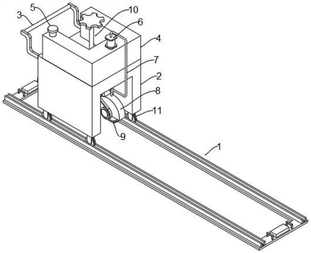
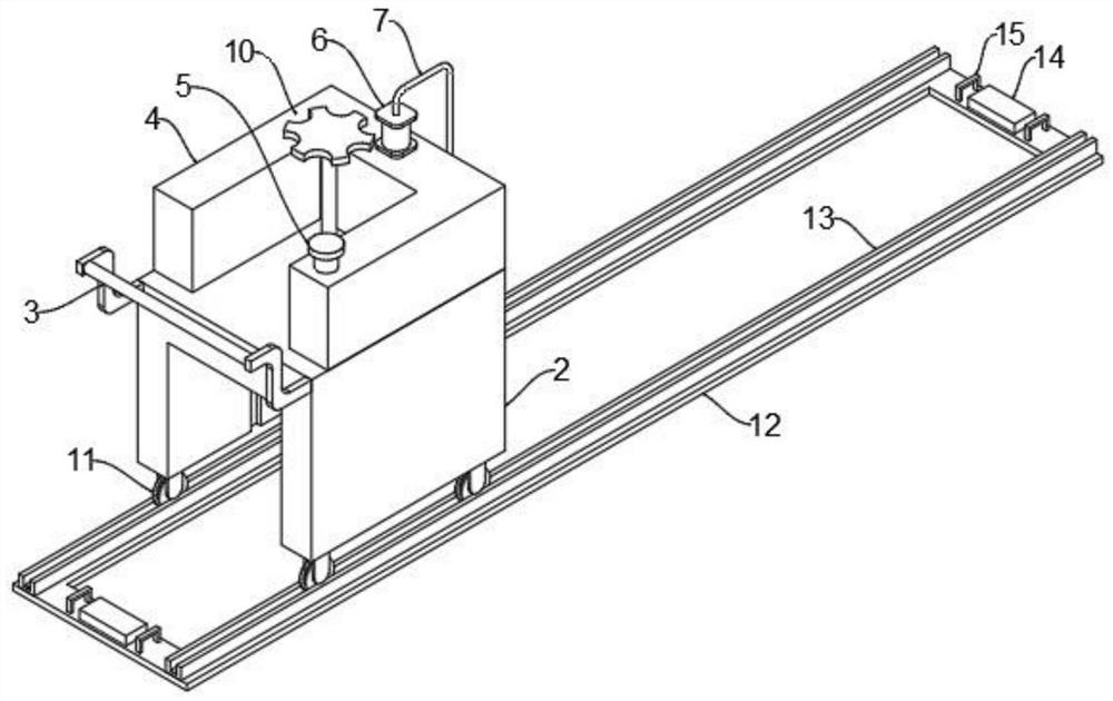
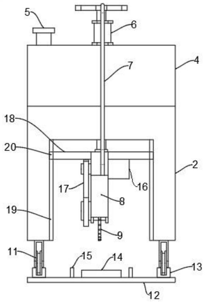
[0035] see Figure 1-8 , in an embodiment of the present invention, a concrete pavement cutting device for highway bridge construction, including a support mechanism 1, the upper surface of the support mechanism 1 is provided with a support 2 moving along its direction, and one side of the support 2 is provided with a push Handle 3, the inside of the bracket 2 is provided with a movable plate 18 that slides up and down with it, and a height adjustment mechanis...


PUM


Abstract

The invention discloses a concrete pavement joint-cutting device for highway bridge construction and a using method thereof. The concrete pavement joint-cutting device comprises a supporting mechanism, wherein a support moving in the direction of the supporting mechanism is arranged on the upper surface of the supporting mechanism; a push handle is arranged on one side of the support; a movable plate sliding up and down with the support is arranged on the inner side of the support; a height adjusting mechanism is arranged between the movable plate and the support; a protective cover is connected to one side of the movable plate through a connecting plate; and a cutting disc is arranged in and rotationally connected with the protective cover. Through cooperation of a bottom plate, guide rails, limiting strips, moving wheels and annular clamping grooves, the support moves in a linear direction all the time in a moving process, so it is guaranteed that a kerf cut by the cutting disc is linear, attractiveness is improved, workers do not need to observe whether the kerf is linear or not all the time, the workers can conduct joint cutting more easily, and then the labor intensity of the workers is reduced.

Description

technical field [0001] The invention relates to the technical field of highway and bridge construction, in particular to a concrete pavement cutting device for highway and bridge construction and a use method thereof. Background technique [0002] Concrete: refers to the collective name of engineering composite materials in which aggregates are cemented into a whole by cementitious materials. Generally speaking, the term concrete refers to the cement concrete obtained by using cement as the cementitious material, sand and stone as the aggregate; mixed with water (may contain admixtures and admixtures) in a certain proportion, and stirred. Concrete, which is widely used in civil engineering. [0003] In the construction of concrete pavement, in order to prevent the thermal expansion and contraction of the pavement due to the extreme low temperature in winter and the extreme high temperature in summer, damage the road, and reduce the service life of the pavement, the concrete...

Claims


Application Information

Patent Timeline
Patent Type & Authority Applications(China)
IPC IPC(8): E01D21/00E01D19/12E01C23/09
CPCE01C23/0933E01D19/125E01D21/00
Inventor 唐春梅
Owner 唐春梅
Why Eureka
Eureka Blog
Learn More