
Thin heat insulation composite heat insulation board and cast-in-place concrete composite wall and construction method

A concrete wall and composite thermal insulation technology, which is applied in the direction of thermal insulation, walls, and building materials, can solve the problems of shortened service life of composite thermal insulation boards and decreased thermal insulation performance of composite walls, and achieve the goal of ensuring thermal insulation performance and service life Effect

Pending Publication Date: 2021-06-18
南京垄基节能科技有限公司
View PDF1 Cites 1 Cited by
  • Summary
  • Abstract
  • Description
  • Claims
  • Application Information

AI Technical Summary

Problems solved by technology

[0005] In order to improve the defects in the related art that the service life of the composite thermal insulation board is shortened and the thermal insulation performance of the composite wall is reduced due to the fact that air is easily poured between the hole and the casing, the application provides a thin thermal insulation composite thermal insulation board and cast-in-place Concrete Composite Wall and Construction Method

Method used


Image

  • Thin heat insulation composite heat insulation board and cast-in-place concrete composite wall and construction method
  • Thin heat insulation composite heat insulation board and cast-in-place concrete composite wall and construction method
  • Thin heat insulation composite heat insulation board and cast-in-place concrete composite wall and construction method

Examples


Embodiment Construction

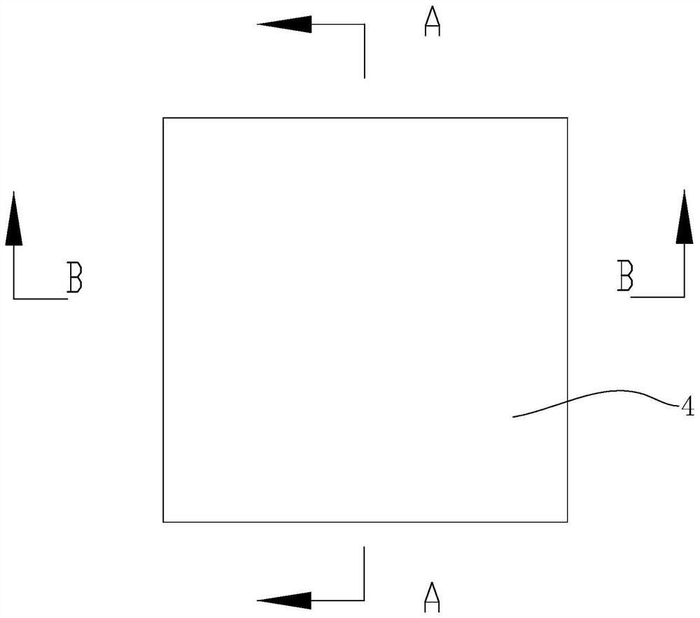
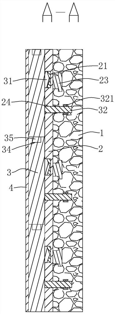
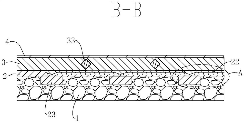
[0038] The following is attached Figure 1-5 The application is described in further detail.

[0039] It is a composite wall made of thin thermal insulation composite thermal insulation board and cast-in-place concrete and its construction method disclosed in the embodiment of the present application.

[0040] refer to figure 1 with figure 2 , the composite wall of thin thermal insulation composite thermal insulation board 3 and cast-in-place concrete, including concrete wall 1 , multiple composite thermal insulation boards 3 and facing layer 4 . The concrete wall 1 is formed by pouring concrete, and a plurality of composite thermal insulation boards 3 are spliced ​​to form a whole composite thermal insulation board 3, and a whole composite thermal insulation board 3 is connected to the concrete wall 1 through connectors, and the facing layer 4 is arranged on the composite thermal insulation board 3. The side of the plate 3 facing away from the concrete wall 1 .

[0041] ...


PUM


Abstract

The invention relates to the field of composite heat insulation walls, and discloses a thin heat insulation composite heat insulation board and cast-in-place concrete composite wall and a construction method. The composite wall comprises a concrete wall body, a plurality of composite heat insulation boards formed by splicing and a facing layer jointly arranged on the sides, away from the concrete wall body, of the plurality of composite heat insulation boards; the concrete wall body and the composite heat insulation boards are connected through connecting pieces; and each connecting piece comprises a connecting plate, wherein the connecting plate is arranged between the concrete wall body and the corresponding composite heat insulation board, an inserting groove is formed in the side, facing the corresponding composite heat insulation board, of the connecting plate, an inserting block is connected to the side, facing the corresponding inserting groove, of the composite heat insulation board, and the inserting block is correspondingly clamped in the inserting groove. The composite wall has the effect of improving the heat insulation performance of the composite heat insulation wall, and the service life of the composite heat insulation wall can be prolonged.

Description

technical field [0001] The application relates to the field of composite thermal insulation walls, in particular to a composite wall composed of thin thermal insulation composite thermal insulation boards and cast-in-place concrete and a construction method. Background technique [0002] At present, in building walls, composite thermal insulation walls are widely used in building walls. Traditional composite thermal insulation walls combine thermal insulation boards with cast-in-place concrete, but this composite thermal insulation wall loses heat during the compounding process. Air bubbles are easily generated between the slab and the cast-in-place concrete, resulting in a hollow shell between the composite thermal insulation wall and shortening the service life. [0003] The Chinese patent with publication number CN103015573A discloses a composite wall of ultra-thin thermal insulation composite thermal insulation board and cast-in-place concrete and its construction method...

Claims


Application Information

Patent Timeline
IPC IPC(8): E04B2/84E04B1/80E04B1/38E04B1/61E04G21/00
CPCE04B1/38E04B1/6137E04B1/80E04B2/84E04G21/00
Inventor 胡圣健邵林王晓龙
Owner 南京垄基节能科技有限公司
Learn More