Ceramic tile soaking device capable of avoiding hollowing

A ceramic tile and hollowing technology, which is applied in the direction of construction and building construction, and can solve problems such as affecting the construction progress, poor bonding, and gaps in the connection between tiles and cement.

Inactive Publication Date: 2021-06-18
侯艳艳
View PDF0 Cites 2 Cited by
  • Summary
  • Abstract
  • Description
  • Claims
  • Application Information

AI Technical Summary

Problems solved by technology

[0002] As we all know, ceramic tiles are an important material for modern building decoration, because there are many fine gaps inside the ceramic tiles, they all have a certain degree of water absorption, if they are directly laid without soaking in water or not soaked in enough water, the tiles will absorb the water in the cement The moisture is absorbed away, so that there will be gaps in the connection between the tile and the cement, and the bond will not be firm, resulting in problems such as hollowing and tile falling off. Due to the different specifications of the tiles, sometimes the top of the tiles cannot be completely soaked because the tiles are too large during construction. The density of the tile itself is also relatively high. Some tiles take a longer time to soak, and the construction time will increase accordingly. Sometimes the tiles will pile up when soaking, and the water cannot fully soak the tiles through the gaps between the tiles, so they need to be re-soaked. Ceramic tiles prolong the construction time and affect the construction progress. When the tiles are soaked, because the tiles are stacked, it is easy to damage the corners of the tiles when they are picked and placed, which not only affects the effect of paving, but also causes additional damage to enterprises or individuals. loss, increased economic pressure

Method used


Image

  • Ceramic tile soaking device capable of avoiding hollowing
  • Ceramic tile soaking device capable of avoiding hollowing
  • Ceramic tile soaking device capable of avoiding hollowing

Examples


specific Embodiment approach

[0027] The present invention can be explained in detail through the following examples, and the purpose of disclosing the present invention is to protect all technical improvements within the scope of the present invention.

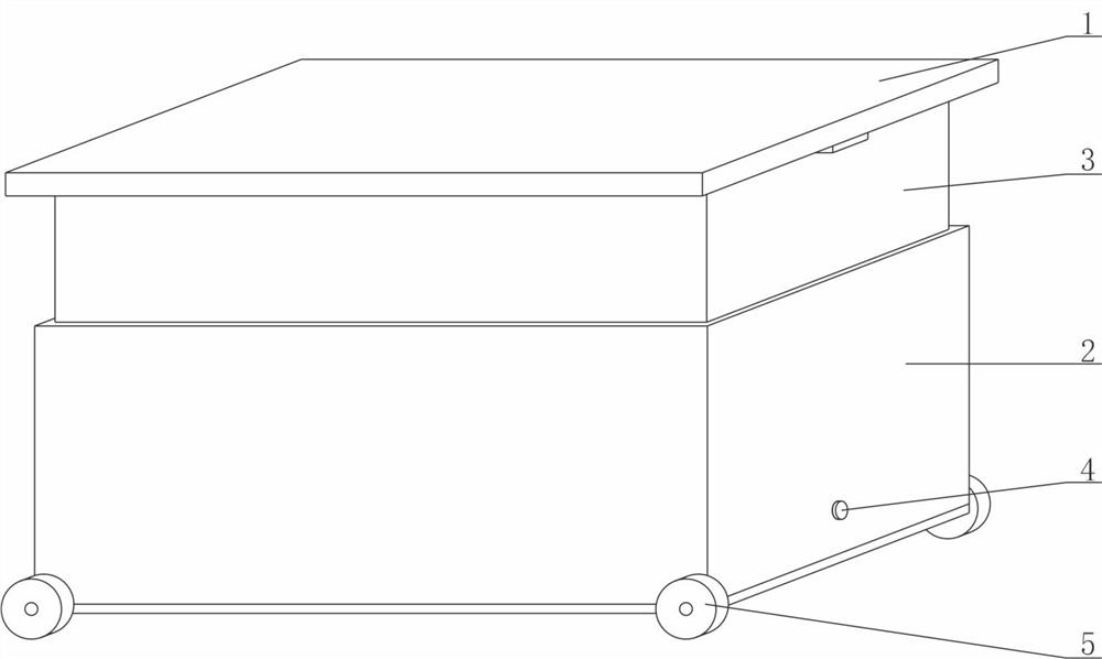
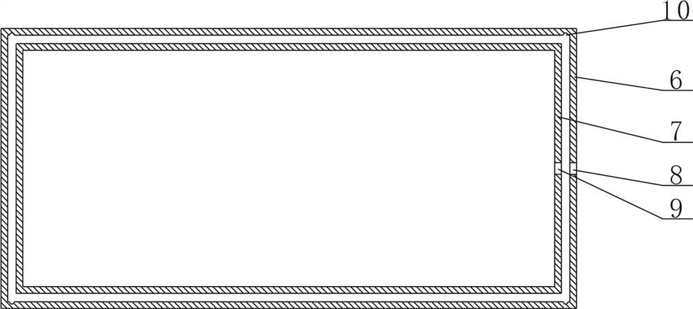
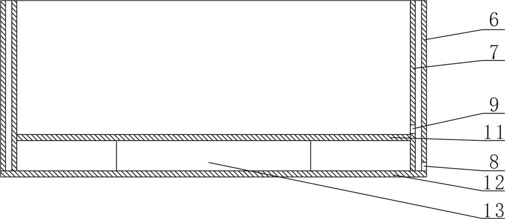
[0028] combined with Figure 1~9 The ceramic tile soaking device that avoids hollowing includes a box body 2, an extension device, a cover plate 1, a fixing plate 15, a support rod 17, a first buffer portion and a second buffer portion, and the box body 2 is provided with an extension device, a fixed plate 15 and a first buffer portion, the fixed plate 15 is provided with a support rod 17, the extension device is provided with a cover plate 1, and the cover plate 1 is provided with a second buffer portion, and the box body 2 is composed of a bottom plate 12, a connecting plate 11. The vibrator 13, the first housing 6, the second housing 7, the support block 14, the wheel 5 and the sealing plug 4 are formed, and the bottom plate 12 is provided with the fir...


PUM


Abstract

The invention provides a ceramic tile soaking device capable of avoiding hollowing, and relates to the field of engineering construction equipment. The device comprises a box body, an extension device, a cover plate, a fixed plate, a support rod, a first buffer part and a second buffer part, the extension device, the fixed plate and the first buffer part are arranged on the box body, the support rod is arranged on the fixed plate, the cover plate is arranged on the extension device, and the second buffer part is arranged on the cover plate. The box body is composed of a bottom plate, a connecting plate, a vibrator, a first shell, a second shell, a supporting block, wheels and a sealing plug, the extension device is composed of a fixing frame, a limiting block and a spring buckle, the first buffer part is composed of a first buffer pad and a clamping block, and the second buffer part is composed of a second buffer pad and a clamping block. The device is simple in structure and convenient to operate, the ceramic tile soaking time can be shortened, water can effectively and rapidly enter ceramic tiles, the four corners and glaze surfaces of the ceramic tiles are prevented from being impacted and damaged, and losses of users are reduced.

Description

technical field [0001] The invention relates to the field of engineering construction equipment, in particular to a ceramic tile soaking device which avoids hollowing. Background technique [0002] As we all know, ceramic tiles are an important material for modern building decoration, because there are many fine gaps inside the ceramic tiles, they all have a certain degree of water absorption, if they are directly laid without soaking in water or not soaked in enough water, the tiles will absorb the water in the cement The moisture is absorbed away, so that there will be gaps in the connection between the tile and the cement, and the bond will not be firm, resulting in problems such as hollowing and tile falling off. Due to the different specifications of the tiles, sometimes the top of the tiles cannot be completely soaked because the tiles are too large during construction. The density of the tile itself is also relatively high. Some tiles take a longer time to soak, and t...

Claims


Application Information

Patent Timeline
IPC IPC(8): E04F21/00
CPCE04F21/00
Inventor 胡光浩侯艳艳张吉昌李鸿岗段育强
Owner 侯艳艳
Why Eureka
Try Eureka