
Combined Wire Rope Guide Mechanism for Rotary Drilling Rig

A technology of rotary drilling rig and guiding mechanism, which is applied in the direction of rotary drilling rig, rotary drilling, clockwork mechanism, etc. It can solve the problems of large space occupation, bending moment, failure, etc., and achieve simplified structure and reduced space The effect of occupying and reducing the bending moment

Active Publication Date: 2021-08-06
XUZHOU XUGONG FOUND CONSTR MACHINERY
View PDF0 Cites 0 Cited by
  • Summary
  • Abstract
  • Description
  • Claims
  • Application Information

AI Technical Summary

Problems solved by technology

[0003] Among them, the sliding rope guide mechanism installs sliding bearings on the inside of the pulley to make the wire rope slide on the longer shaft to meet the requirements of the incident angle when the wire rope moves from one side of the drum to the other, but this mechanism is not perpendicular to the pulley due to the force angle Therefore, the pulley needs to be subjected to bending moment during the working process, so that the sliding bearing in the pulley is easily worn into a bell mouth shape and fails
[0004] The swing mechanism meets the requirements of the incident angle when the steel wire rope moves from one side of the drum to the other by swinging around the hinged seat welded on the drill mast. This mechanism can ensure that the force direction of the pulley and the steel wire rope is always perpendicular, but its It takes up a lot of space, and other wire rope guide mechanisms cannot be arranged in its swing space

Method used


Image

  • Combined Wire Rope Guide Mechanism for Rotary Drilling Rig
  • Combined Wire Rope Guide Mechanism for Rotary Drilling Rig
  • Combined Wire Rope Guide Mechanism for Rotary Drilling Rig

Examples


Embodiment Construction

[0017] The following will clearly and completely describe the technical solutions in the embodiments of the present invention with reference to the accompanying drawings in the embodiments of the present invention. Obviously, the described embodiments are only some, not all, embodiments of the present invention. Based on the embodiments of the present invention, all other embodiments obtained by persons of ordinary skill in the art without making creative efforts belong to the protection scope of the present invention.

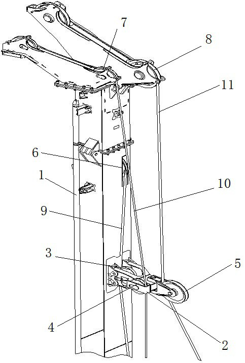
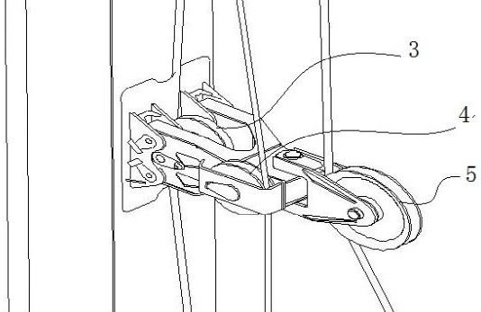
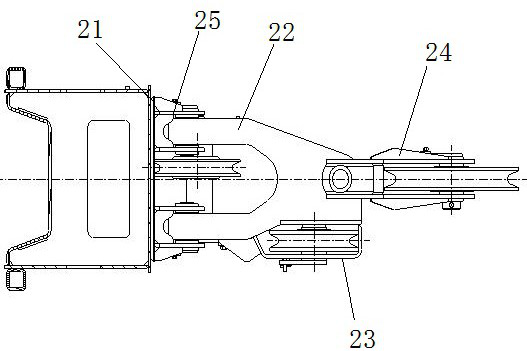
[0018] Such as figure 1 , figure 2 As shown, a combined wire rope guiding mechanism of a rotary drilling rig, a pressurized hoisting wire rope pulley 6 , an auxiliary hoisting goose head pulley 7 and a main hoisting pulley 8 are arranged on the drill mast 1 . In the direction of the cross-section of the drill mast 1 , the auxiliary hoisting goose pulley 7 is located outside the pressurized hoisting wire rope pulley 6 , and the main hoisting pulley 8 is locat...


PUM


Abstract

The invention discloses a combined wire rope guiding mechanism of a rotary drilling rig. The drill mast is equipped with a pressurized winch wire rope pulley, auxiliary winch goose head pulley and main winch pulley; a bracket is fixed in the middle of the drill mast, and a pressurized guide rope pulley, auxiliary coil guide rope pulley and main coil guide are installed on the bracket. Rope pulley; in the direction of the cross-section of the drill mast, the auxiliary coil guide rope pulley is located outside the pressurized guide rope pulley, and the main coil guide rope pulley is located outside the auxiliary coil guide rope pulley. The invention divides the guiding space of each steel wire rope into three levels, which are independent of each other, and the structure is simplified to reduce space occupation; The guide rope mechanism is arranged in the space on the lower two floors to reduce the bending moment on the pulley during the working process; the main hoist load is large and the use is frequent, and the incident angle of the wire rope changes greatly, so the main hoist rope guide mechanism is arranged at the lowest position. In the outer layer, the rope guide mechanism is designed to swing to ensure the stress state of the wire rope and the pulley of the guide mechanism.

Description

technical field [0001] The invention relates to a rotary drilling rig, in particular to a combined wire rope guiding mechanism of the rotary drilling rig. Background technique [0002] Rotary drilling rig wire ropes generally include main hoisting wire ropes, auxiliary hoisting wire ropes, and pressurized hoisting wire ropes. The steel wire rope is generally retracted and unwound through the winch mechanism. At present, the main winch in the field of rotary drilling rigs generally uses a single-row rope main winch. With the lowering of the steel wire rope in the working room, the steel wire rope rolls from one side of the drum to the other side of the drum, and the incident angle of the steel wire rope winding pulley will change greatly, and the steel wire rope winding pulley has higher requirements on the incident angle. Therefore, the rotary drilling rig needs a rope guide mechanism to guide the wire rope so that its incident angle meets the requirements of use. At pres...

Claims


Application Information

Patent Timeline
Patent Type & Authority Patents(China)
IPC IPC(8): E21B19/02E21B3/00B66D1/36
CPCB66D1/36E21B3/00E21B19/008E21B19/02
Inventor 王海金张继光孙余单昌猛刘丽娟
Owner XUZHOU XUGONG FOUND CONSTR MACHINERY
Learn More