Medium-high pressure screw compressor

A screw compressor, medium and high pressure technology, applied in the field of compressors and screw compressors, can solve the problems of increasing the volume of the oil separator of the compressor, reducing the exhaust efficiency of the compressor, reducing the working efficiency of the compressor, etc. Small, good effect, smooth exhaust effect

Inactive Publication Date: 2021-06-18
李博志
View PDF10 Cites 0 Cited by
  • Summary
  • Abstract
  • Description
  • Claims
  • Application Information

AI Technical Summary

Problems solved by technology

[0004] However, after reducing the flow rate of the oil-air mixture, the exhaust efficiency of the compressor will decrease. If the gas in the oil separator barrel is not discharged in time, the working efficiency of the compressor will be reduced and the normal operation of downstream equipment will be affected. Therefore, during the exhaust process It is also necessary to improve the exhaust efficiency to ensure the demand of downstream equipment, especially the circulation demand in the circulation system and reduce the suction power of the compressor. This adverse effect is more obvious for medium and high pressure compressors
[0005] In addition, the oil-air mixture can be filtered multiple times by setting multi-layer filter screens to improve the separation effect, but this will lead to an increase in the volume of the oil separator barrel of the compressor

Method used


Image

  • Medium-high pressure screw compressor
  • Medium-high pressure screw compressor
  • Medium-high pressure screw compressor

Examples


Embodiment Construction

[0042] In order to make the above objects, features and advantages of the present invention more comprehensible, specific embodiments of the present invention will be described in detail below in conjunction with the accompanying drawings.

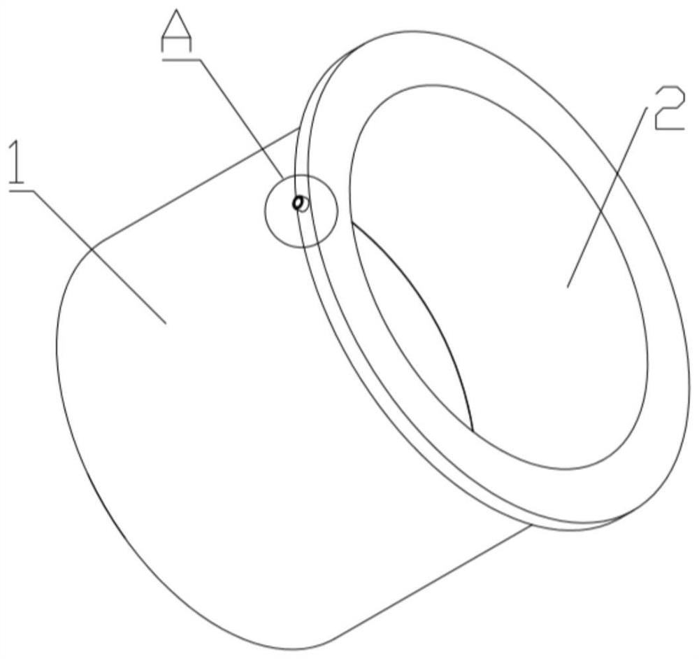
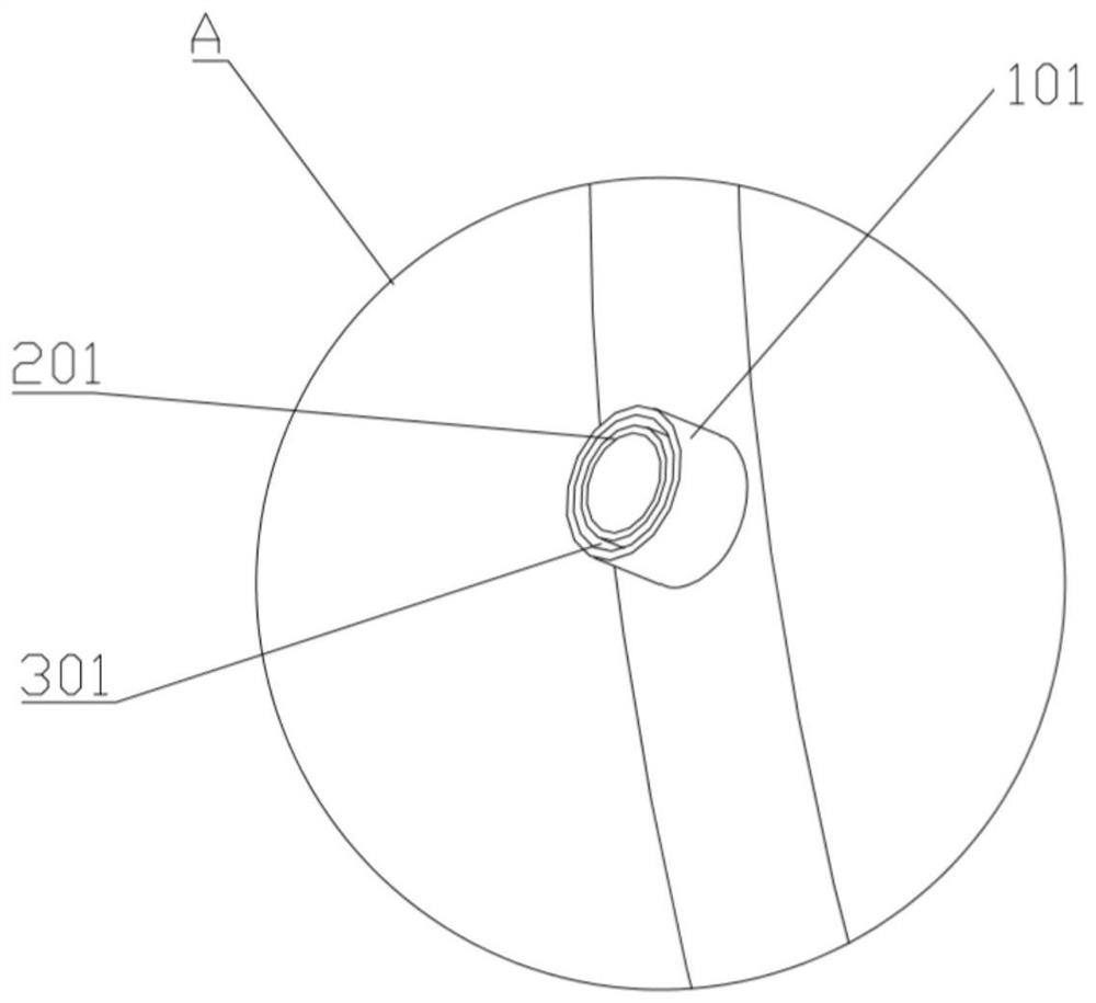
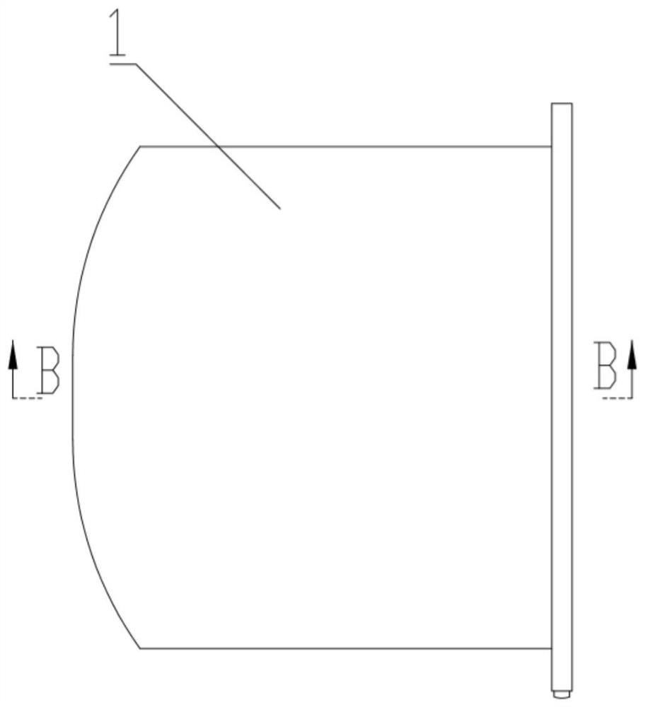
[0043] Such as Figure 1-19 As shown, a medium-high pressure screw compressor includes a pair of female and male screw rotors arranged in parallel and capable of meshing with each other, a motor that drives the screw rotors to rotate, a capacity control valve that can change the volume ratio, and a capacity control valve that can control the volume ratio of the motor. The inverter for changing the rotational speed, the oil separation barrel capable of separating the oil-air mixture, and the outer casing arranged on the outer surface of the compressor.

[0044] In addition, the medium and high pressure screw compressor also includes an air filter, an intake controller, a cooler, and the like. When the medium and high pressure screw compres...


PUM


Abstract

The invention provides a medium-high pressure screw compressor. The medium-high pressure screw compressor comprises a screw rotor, a motor and an oil separation barrel, wherein the oil separation barrel comprises an outer barrel and an inner barrel, the inner barrel is arranged inside the outer barrel in a sleeve mode, a hollow gap layer is arranged between the outer barrel and the inner barrel, a multi-stage filtering device is arranged in the inner barrel, a single-stage filtering device is arranged in the gap layer, an inner exhaust port is formed in the inner barrel, an outer exhaust port is formed in the outer cylinder, the inner exhaust port is arranged in the outer exhaust port in a sleeve mode, a hollow annular cavity is formed between the inner exhaust port and the outer exhaust port, after an oil-gas mixture enters the inner barrel, part of the oil-gas mixture enters the multi-stage filtering device to be filtered and is discharged through the inner exhaust port, and the remaining oil-gas mixture enters the gap layer and is discharged through the annular cavity after being filtered through the single-stage filtering device. The medium-high pressure screw compressor has the advantages that the oil-gas separation effect is good, exhaust is smooth, and the occupied space of the filtering device is small.

Description

technical field [0001] The invention relates to a compressor, in particular to a screw compressor, in particular to a medium-high pressure screw compressor. Background technique [0002] In the screw compressor, there will be a device or structure for separating oil and gas, such as an oil separation barrel. The separation effect of oil and gas directly affects the performance and reliability of the screw compressor, so improving the oil separation effect has always been one of the main goals pursued by the design of the screw compressor. [0003] At present, the built-in oil separation barrel of the screw compressor often adopts the separation structure of the oil separation filter, which relies on the dense mesh structure to form resistance to the flow of the oil-gas mixture, reduces the flow rate of the oil-gas mixture, and achieves separation through adsorption and filtration. Purpose. Among them, the effect of oil-gas separation is related to the flow rate of the air ...

Claims


Application Information

Patent Timeline
Patent Type & Authority Applications(China)
IPC IPC(8): F04C29/02F04C18/16F04C23/02
CPCF04C29/026F04C18/16F04C23/02
Inventor 不公告发明人
Owner 李博志
Why Eureka
Try Eureka