Pipe pushing device

A pipe and pipe gripper technology, which is applied in the direction of pipe laying and maintenance, pipes/pipe joints/fittings, mechanical equipment, etc. It can solve problems such as pipe pushing, pipe gripper bending, and pipe gripper weight. Achieve the effect of prolonging service life and reducing wear

Active Publication Date: 2021-06-18
BC P INC CHINA NAT PETROLEUM CORP +2
View PDF9 Cites 0 Cited by
  • Summary
  • Abstract
  • Description
  • Claims
  • Application Information

AI Technical Summary

Problems solved by technology

[0004] However, the weight of the pipe gripper is often relatively large. When the diameter of the pipe is small, the pipe is easily bent by the pipe gripper during laying, which makes it difficult to push the pipe into the formed hole accurately

Method used


Image

  • Pipe pushing device
  • Pipe pushing device
  • Pipe pushing device

Examples


Embodiment Construction

[0049] In order to make the purpose, technical solution and advantages of the present application clearer, the implementation manners of the present application will be further described in detail below in conjunction with the accompanying drawings.

[0050] Before explaining the embodiment of the present application in detail, the application scenario of the embodiment of the present application will be described first.

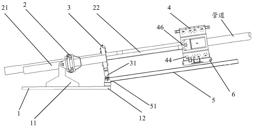
[0051] With the maturity of the pipeline laying technology, the application range of the pipe pushing device can be expanded by utilizing the pushing and pulling function of the pipe pushing device to the pipeline. For example, when there is a problem in the directional drilling pipeline laying process, the pipe pushing device can pull out the pipeline in the hole together with the tunnel boring machine, so as to realize the emergency construction of the directional drilling pipeline; When crossing, use the pipe pushing device on land to push the pipeline to c...


PUM


Abstract

The invention discloses a pipe pushing device, and belongs to the technical field of pipeline non-excavation. The device comprises a base, a main pushing oil cylinder, a first righting frame, a pipe clamping device, a sliding rail and a sliding piece. A cylinder body in the main pushing oil cylinder is connected with the first part of the base, the first end of a piston rod in the main pushing oil cylinder is located in the cylinder body, the second end of the piston rod is connected with a connecting base of the pipe clamping device, and the pipe clamping device is used for clamping a pipeline. The bottom of the first righting frame and the second part of the base are both connected with the first end of the sliding rail, and the first righting frame is used for limiting the radial displacement of the pipeline clamped by the pipe clamping device. The frame of the pipe clamping device is connected with the sliding piece, and the sliding piece makes contact with a track of the sliding rail and can move on the track of the sliding rail. Thus, when pipe pushing construction is carried out, the weight of the pipe clamping device can be borne by the sliding rail, and therefore the pipeline cannot be bent by the pipe clamping device. Due to the fact that the first righting frame can limit the pipeline in the radial direction, the pipeline can be accurately pushed into a formed hole.

Description

technical field [0001] The present application relates to the technical field of non-excavation pipelines, in particular to a pipe pushing device. Background technique [0002] During the pipeline laying process, pipe jacking machines and pipe pushers are often used to push the pipe into the formed hole. Specifically, the pipe jacking machine is welded to one end of the pipe, and the pipe pushing device is clamped on the outer wall of the pipe. In the holes, the pipeline can be installed in place at one time. [0003] At present, the pipe pushing device includes a base, a main push cylinder and a pipe gripper. Specifically, the cylinder body in the main push cylinder is connected to the base, and the piston rod in the main push cylinder is connected to the connecting seat of the pipe gripper. When in use, first fix the base and connect the base with the cylinder body of the main push cylinder, then clamp the clamp on the outer wall of the pipeline, and connect the connecti...

Claims


Application Information

Patent Timeline
Patent Type & Authority Applications(China)
IPC IPC(8): F16L1/028F16L1/12
CPCF16L1/028F16L1/12
Inventor 江勇焦如义周号隋付东刘厚平武涛张倩刘艳利
Owner BC P INC CHINA NAT PETROLEUM CORP
Why Eureka
Try Eureka