Flexible display module and flexible display device
A flexible display and module technology, applied in the direction of identification devices, instruments, etc., can solve the problems of flexible screen wear, sliding, and unevenness, and achieve the effects of avoiding friction, improving smoothness, and stabilizing the guiding effect
- Summary
- Abstract
- Description
- Claims
- Application Information
AI Technical Summary
Problems solved by technology
Method used
Image

Examples
Embodiment Construction
[0037] The following descriptions of the various embodiments refer to the accompanying drawings to illustrate specific embodiments in which the invention may be practiced. The directional terms mentioned in the present invention, such as [top], [bottom], [front], [back], [left], [right], [inside], [outside], [side], etc., are only for reference The orientation of the attached schema. Therefore, the directional terms used are used to illustrate and understand the present invention, but not to limit the present invention. In the figures, structurally similar elements are denoted by the same reference numerals. In the drawings, the thicknesses of some layers and regions are exaggerated for clear understanding and ease of description. That is, the size and thickness of each component shown in the drawings are arbitrarily shown, but the present invention is not limited thereto.
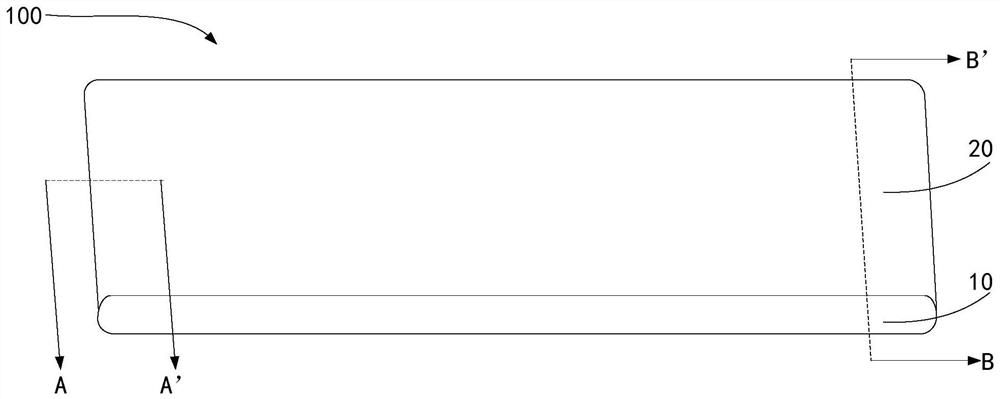
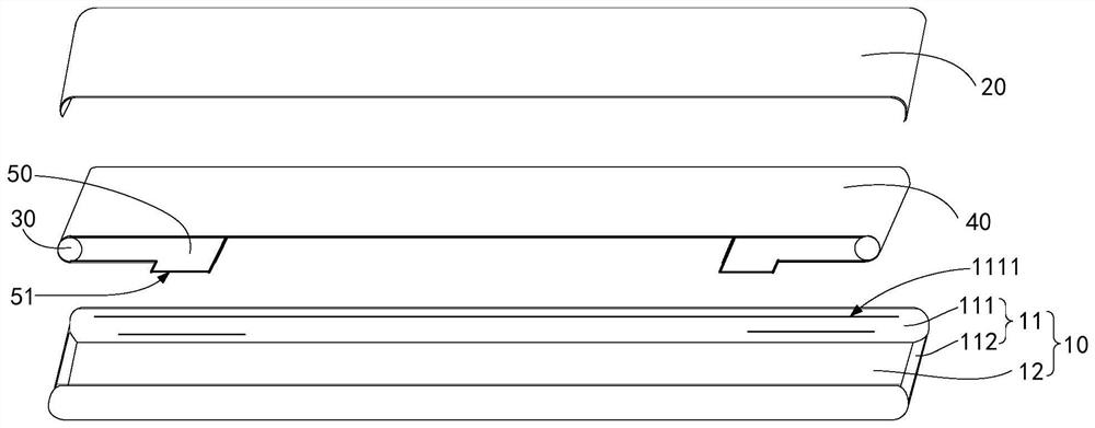
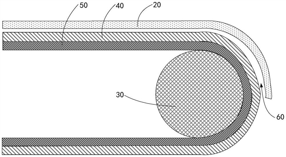
[0038] figure 1 It is a schematic diagram of the overall structure of the flexible display module p...
PUM
 Abstract
Description
Claims
Application Information
 - Generate Ideas
- Intellectual Property
- Life Sciences
- Materials
- Tech Scout
- Unparalleled Data Quality
- Higher Quality Content
- 60% Fewer Hallucinations
Browse by: Latest US Patents, China's latest patents, Technical Efficacy Thesaurus, Application Domain, Technology Topic, Popular Technical Reports.
© 2025 PatSnap. All rights reserved.Legal|Privacy policy|Modern Slavery Act Transparency Statement|Sitemap|About US| Contact US: help@patsnap.com