Supercharge Your Innovation With Domain-Expert AI Agents!

Frequency reduction and communication device

A frequency reduction, metal resonant cavity technology, applied in the direction of circuits, waveguide devices, electrical components, etc., can solve the problems of increasing the size of the filter, increasing the complexity of the resonating column, increasing the cost of the filter, etc., and achieving low resonance frequency Effect

Pending Publication Date: 2021-06-18
COMBA RF TECH GUANGZHOU LTD +1
View PDF0 Cites 0 Cited by
  • Summary
  • Abstract
  • Description
  • Claims
  • Application Information

AI Technical Summary

Problems solved by technology

However, the method of setting the disc on the top of the resonant column increases the complexity of the resonant column. In addition, the resonant cavity will increase the size of the filter, and both methods will increase the cost of the filter.

Method used


Image

  • Frequency reduction and communication device
  • Frequency reduction and communication device
  • Frequency reduction and communication device

Examples


Embodiment Construction

[0026] In order to make the above objects, features and advantages of the present invention more comprehensible, specific implementations of the present invention will be described in detail below in conjunction with the accompanying drawings. In the following description, numerous specific details are set forth in order to provide a thorough understanding of the present invention. However, the present invention can be implemented in many other ways different from those described here, and those skilled in the art can make similar improvements without departing from the connotation of the present invention, so the present invention is not limited by the specific embodiments disclosed below.

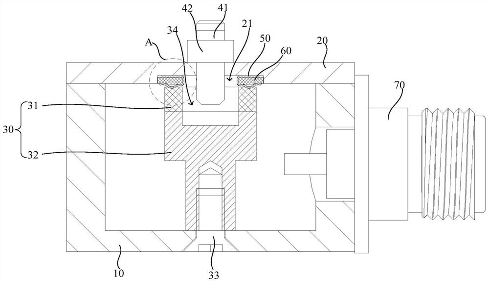
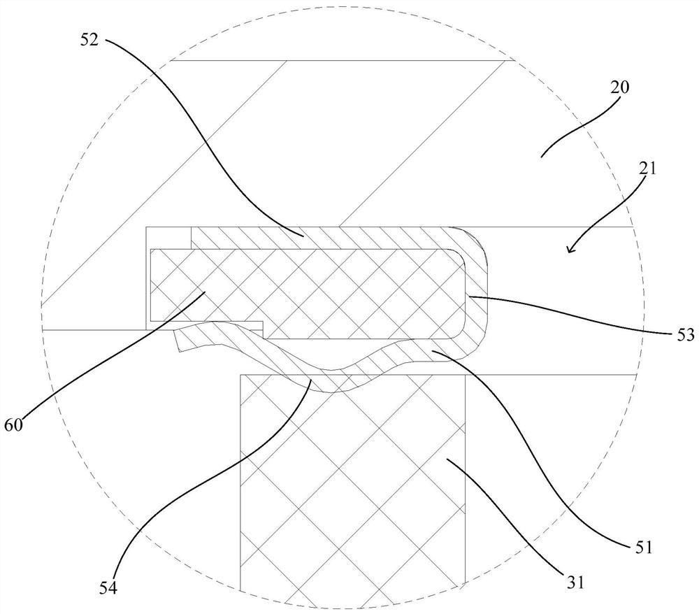
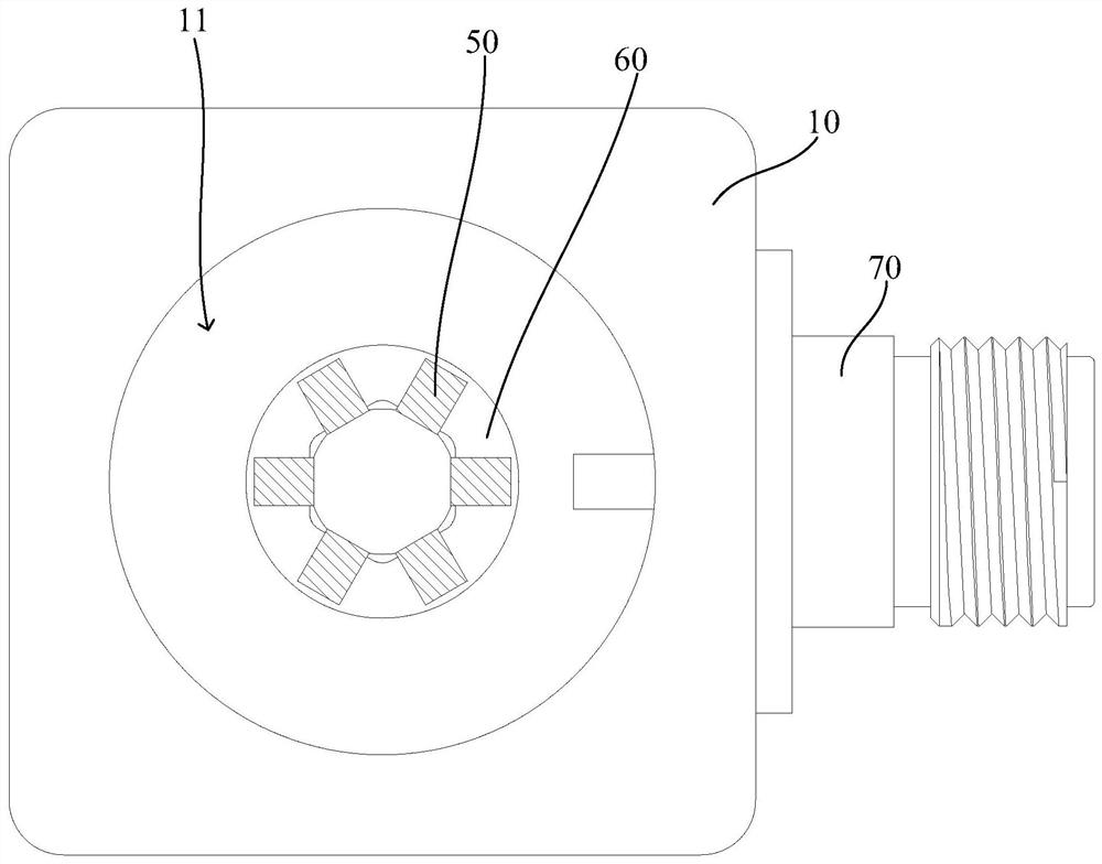
[0027] refer to Figure 1 to Figure 3 , figure 1 shows an axial sectional structure diagram of a frequency reducing device according to an embodiment of the present invention, figure 2 show figure 1 The enlarged schematic diagram of the structure at A, image 3 It shows a top structu...


PUM


Abstract

The invention relates to a frequency reduction device and a communication device. The frequency reduction device comprises a metal resonant cavity, a metal cover body and a resonant column, wherein the top of the metal resonant cavity is provided with an opening, and the metal cover body covers the opening; the bottom of the resonant column is fixedly arranged on a bottom wall of the metal resonant cavity; the resonant column comprises a dielectric column; and a top surface of the dielectric column is contacted with the metal cover body. According to the frequency reduction device, the resonant column comprises the dielectric column and is in contact with the metal cover body through a top surface of the dielectric column, namely, a medium is loaded on the resonant column, or the whole resonant column adopts the dielectric column, so the resonant frequency lower than that of a conventional form is realized under a smaller single-cavity size.

Description

technical field [0001] The invention relates to the technical field of communication products, in particular to a frequency reduction device and a communication device. Background technique [0002] Cavity filters are widely used in the field of communication products, and their basic functions are: to allow useful signals to pass through the signal chain to the greatest extent, and to suppress useless signals to the greatest extent. There are generally two ways to reduce the frequency of traditional filters: one is to change the structure of the resonant column, that is, to set a disc on the top of the resonant column, and the disc is matched with the metal cover to reduce the resonance in this way. Frequency; the other is to reduce the frequency by increasing the volume of the resonant cavity, or use both methods at the same time. However, the method of setting the disk on the top of the resonant column increases the complexity of the resonant column. In addition, the enl...

Claims


Application Information

Patent Timeline
Patent Type & Authority Applications(China)
IPC IPC(8): H01P1/207
CPCH01P1/207
Inventor 陈安
Owner COMBA RF TECH GUANGZHOU LTD
Features
  • R&D
  • Intellectual Property
  • Life Sciences
  • Materials
  • Tech Scout
  • Unparalleled Data Quality
  • Higher Quality Content
  • 60% Fewer Hallucinations
Learn More