Profiled brace, in particular for motor vehicle

A technology for motor vehicles and supports, applied in the direction of vehicle components, connections between superstructure sub-assemblies, superstructures, etc., can solve the problems of load transmission, high cost, stiffness loss and weight increase, and achieve economical manufacturing, Avoidance of welded connections, effect of improved corrosion resistance

Active Publication Date: 2021-06-18
BAYERISCHE MOTOREN WERKE AG
View PDF15 Cites 0 Cited by
  • Summary
  • Abstract
  • Description
  • Claims
  • Application Information

AI Technical Summary

Problems solved by technology

In addition, the welding process is costly
[0009] Flange connections on one side have the disadvantage that the applied loads cannot be transferred via the second flange, which means a loss of stiffness and an increase in weight

Method used


Image

  • Profiled brace, in particular for motor vehicle
  • Profiled brace, in particular for motor vehicle

Examples


Embodiment Construction

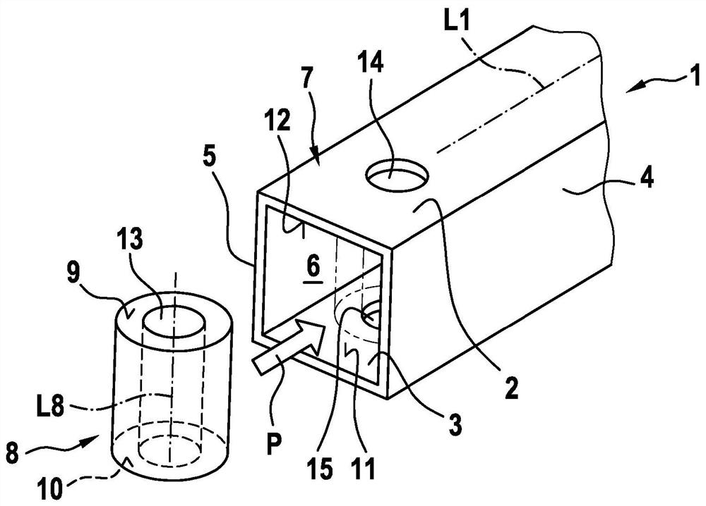
[0031] exist figure 1 1 shows a schematically simplified partial perspective view of a profile support 1 according to the invention, which may be, for example, a part of a bodywork of a motor vehicle.

[0032] The profile support 1 has an upper flange 2 and a lower flange 3 which extend at a distance from each other and parallel to one another over the entire length of the profile support 1 . However, profile supports that do not have a constant cross section are also conceivable. The upper flange 2 and the lower flange 3 are connected by means of side walls 4 and 5 spaced apart according to their width, which together with the upper flange 2 and the lower flange 3 delimit an interior space 6 of the profile support 1 .

[0033] also, figure 1 The profile end 7 of the profile support 1 is shown, into which the end piece 8 can be inserted, which is indicated by the arrow P. FIG.

[0034] The end piece 8 is here dimensioned such that, in the inserted state, its two end faces ...


PUM


Abstract

The invention relates to a profiled brace (1), in particular for a motor vehicle, comprising a top chord (2); a bottom chord (3); two mutually spaced lateral walls (4, 5) which together with the top chord (2) and the bottom chord (3) delimit an interior (6); two profiled ends (7, 16); and an end piece (8A, 8B) which is arranged in each profiled end (7, 16), the end pieces being connected together by means of a connecting web (18), wherein the end face (9, 10) of each end piece (8A, 8B) rests against adjacent inner wall regions (11 and 12) of the bottom chord (3) and the top chord (2), respectively, and an intermediate region (17) which is designed as a tunnel that is introduced into the bottom chord (3) is formed between the profiled ends (7, 16).

Description

technical field [0001] The invention relates to a profile support according to the preamble of claim 1 , in particular provided for a motor vehicle. Background technique [0002] A profile support of this type, as known for example from DE 21 05 090 A, can be a component part of the bodywork of a motor vehicle and be used, for example, as a tension-extrusion support. [0003] Other known profile supports have extruded or extruded profile ends by means of inserts (tube-in-tube), or are designed with extruded profile ends with welded spacer sleeves. [0004] An alternative embodiment has an unpressed end with a welded counterpart. Alternatives have profile ends with welded multi-part end pieces or include push-through bushings welded to the flanges. [0005] Furthermore, solid material supports and support connections on the flanges, for example by means of compression nuts, are known. [0006] In the case of severe compression of the profile end there is the disadvantage o...

Claims


Application Information

Patent Timeline
Patent Type & Authority Applications(China)
IPC IPC(8): B60R19/26B60R19/34B60R19/24B62D21/15
CPCB60R19/26B60R19/34B60R19/24B62D21/152B62D25/00B62D27/065
Inventor M·海辛格D·塔希尼茨
Owner BAYERISCHE MOTOREN WERKE AG
Why Eureka
Try Eureka