Supercharge Your Innovation With Domain-Expert AI Agents!

Ceramic electronic component

A technology of electronic components and ceramics, applied in the field of ceramic electronic components, can solve the problems of low adhesion strength of terminal electrodes and other problems

Pending Publication Date: 2021-06-18
MURATA MFG CO LTD
View PDF7 Cites 0 Cited by
  • Summary
  • Abstract
  • Description
  • Claims
  • Application Information

AI Technical Summary

Problems solved by technology

However, in the peripheral portion of the terminal electrode not covered by the coating layer, the adhesion strength of the terminal electrode becomes low.
[0009] In addition, when a part of the peripheral portion of the terminal electrode is covered with the coating layer instead of covering the entire circumference of the peripheral portion of the terminal electrode, since the stress concentrates on the portion where the terminal electrode and the coating layer overlap, the terminal electrode is easy to for example Towards Figure 12 The direction of the arrow shown shrinks the terminal electrode stripping

Method used


Image

  • Ceramic electronic component
  • Ceramic electronic component
  • Ceramic electronic component

Examples


Embodiment Construction

[0025] Hereinafter, the ceramic electronic component of the present invention will be described.

[0026] However, the present invention is not limited to the following configurations, and can be appropriately changed and applied within a range that does not change the gist of the present invention. Moreover, the structure which combined two or more of each preferable structure described below is also this invention.

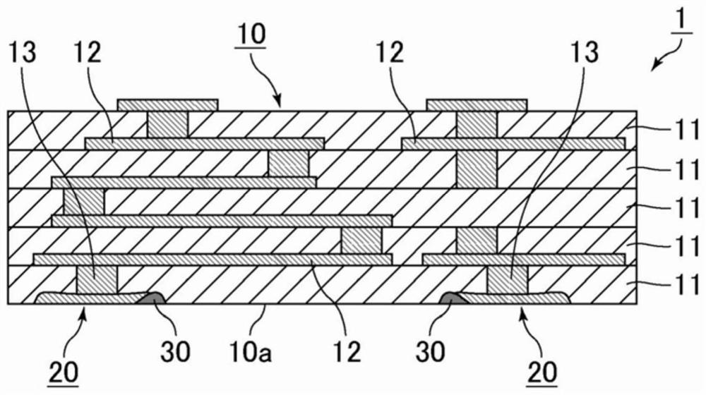
[0027] The ceramic electronic component of the present invention is a ceramic electronic component that can be mounted on a mounting substrate. The present invention can be applied to various laminated ceramic electronic components such as multilayer ceramic substrates, for example. However, the ceramic electronic component of the present invention is not limited to a laminated structure, and may have a single-layer structure.

[0028] figure 1 It is a cross-sectional view schematically showing a ceramic electronic component according to one embodiment of th...


PUM

PropertyMeasurementUnit
thicknessaaaaaaaaaa
thicknessaaaaaaaaaa
thicknessaaaaaaaaaa

Abstract

This ceramic electronic component is provided with: a component body including a ceramic layer; at least one terminal electrode disposed on one main surface of the component body; and an insulating coating layer disposed across the ceramic layer and the terminal electrode so as to cover not all but a part of the periphery of the terminal electrode. When viewed in plan from the one main surface of the component body, the coating layer intersects the terminal electrode at a non-vertical angle in an intersecting portion in which the terminal electrode not covered with the coating layer intersects the coating layer.

Description

technical field [0001] This invention relates to ceramic electronic components. Background technique [0002] As an example of a ceramic electronic component mounted on a mounting substrate, Patent Document 1 discloses a ceramic electronic component including a component main body and an external terminal electrode provided along the main surface of the component main body, and the external terminal electrode has a peripheral edge part and a central part surrounded by the peripheral part, the thickness of the peripheral part is thicker than that of the central part, and at least a part of the peripheral part is buried in the component main body. Patent Document 1 describes that an electrically insulating coating layer is preferably formed along the main surface of the component body so as to cover at least a part of the peripheral portion of the external terminal electrode. [0003] Patent Document 1: International Publication No. 2012 / 157436 [0004] As described in Paten...

Claims


Application Information

Patent Timeline
Patent Type & Authority Applications(China)
IPC IPC(8): H05K3/28H01G4/228H01G4/30H05K1/16H05K3/46
CPCH01G4/228H01G4/30H05K1/113H05K2201/0376H05K2201/09154H05K2201/09145H05K3/4007H05K1/0298H05K1/0306H05K1/115H05K2201/099H05K2201/09909H05K2203/0597
Inventor 村北直哉大坪喜人山元一生森本裕太
Owner MURATA MFG CO LTD
Features
  • R&D
  • Intellectual Property
  • Life Sciences
  • Materials
  • Tech Scout
  • Unparalleled Data Quality
  • Higher Quality Content
  • 60% Fewer Hallucinations
Learn More