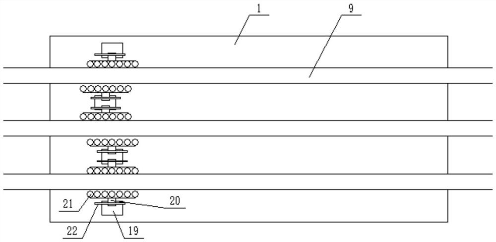
Steel bar tensioning device used in building construction

A technology of building construction and stretching device, which is applied in the direction of manufacturing tools, metal wire drawing, metal processing equipment, etc., can solve problems such as low stretching efficiency, uneven force, safety accidents, etc., to ensure safety and stability, The effect of uniform force and improved efficiency

Active Publication Date: 2022-04-15
BAOYE HUBEI CONSTR ENG GRP
View PDF0 Cites 0 Cited by
  • Summary
  • Abstract
  • Description
  • Claims
  • Application Information

AI Technical Summary

Problems solved by technology

The existing steel bar stretching equipment has the following problems: 1) only one steel bar can be stretched at a time, and the stretching efficiency is low; 2) for longer steel bar stretching, if the traditional clamping bar ends are used for Stretching, due to the self-weight of the steel bar and the long steel bar that needs to be stretched in the middle, the stress is uneven, and the final tensile strength may be inconsistent; 3) The steel bar cannot be continuously clamped during stretching. During the process, the clamping mechanism loosens, etc., which will lead to damage to the steel bar or safety accidents; 4) The steel bar may bend after being stretched, so it is necessary to straighten the stretched steel bar in the later stage

Method used


Image

  • Steel bar tensioning device used in building construction
  • Steel bar tensioning device used in building construction
  • Steel bar tensioning device used in building construction

Examples


Embodiment Construction

[0032] The present invention will be further described in detail below in conjunction with the accompanying drawings, so that those skilled in the art can implement it with reference to the description.

[0033] It should be noted that the experimental methods described in the following embodiments, unless otherwise specified, are conventional methods, and the reagents and materials, if not otherwise specified, can be obtained from commercial sources; in the description of the present invention, The terms "landscape", "portrait", "top", "bottom", "front", "rear", "left", "right", "vertical", "horizontal", "top", "bottom", The orientation or positional relationship indicated by "inner", "outer", etc. is based on the orientation or positional relationship shown in the drawings, which is only for the convenience of describing the present invention and simplifying the description, and does not indicate or imply that the referred device or element must have Certain orientations, co...


PUM


Abstract

The invention discloses a steel bar stretching device used in building construction, comprising: a base, the upper surface of which is provided with a plurality of recessed sliding tables at intervals, and the sliding table just accommodates a rack to pass through horizontally. The rack is matched with the gear; the clamping mechanism includes a moving block and a matching block. The upper surface of the moving block is provided with a plurality of concave arc-shaped bottom grooves at intervals, and the lower parts of the multiple steel bars are respectively fitted in a plurality of arc-shaped bottom grooves Among them, after the two ends of the matching block respectively pass through the abutting grooves of the fixed block provided above the moving block, the multiple arc-shaped top grooves of the described matching block coincide with the multiple arc-shaped bottom grooves one by one. a steel bar, and the lower end of the screw is tightly against the matching block. The invention is a steel bar stretching device integrating multiple functions, which has simple structure, convenient operation, high stretching efficiency, high safety, good steel bar stretching effect, can meet the actual construction requirements and can simultaneously realize the stretching of steel bars Subsequent straighter function.

Description

technical field [0001] The invention relates to the technical field of building construction equipment. More particularly, the present invention relates to reinforcement tensioning devices for use in building construction. Background technique [0002] In building construction, it is often necessary to pre-stretch steel bars to achieve a specific length and prestress before construction. At present, the most commonly used method is to stretch through steel bar stretching equipment. The existing steel bar stretching equipment has the following problems: 1) only one steel bar can be stretched at a time, and the stretching efficiency is low; 2) for longer steel bar stretching, if the traditional clamping bar ends are used for Stretching, due to the self-weight of the steel bar and the long steel bar that needs to be stretched in the middle, the stress is uneven, and the final tensile strength may be inconsistent; 3) The steel bar cannot be continuously clamped during stretchi...

Claims


Application Information

Patent Timeline
Patent Type & Authority Patents(China)
IPC IPC(8): B21C1/02B21C19/00B21F1/02
CPCB21C1/02B21C19/00B21F1/02
Inventor 李峰高林王昕姚攀郑啟翔邵巍黄荣凯徐旭东周超
Owner BAOYE HUBEI CONSTR ENG GRP
Why Eureka
Try Eureka