Metal plate stamping device

A stamping device and metal sheet technology, applied in the field of stamping equipment, can solve problems such as troublesome operation and affecting sheet metal stamping efficiency, and achieve the effect of improving stamping efficiency

Pending Publication Date: 2021-06-22
杭州临安荣升机械有限公司
View PDF0 Cites 0 Cited by
  • Summary
  • Abstract
  • Description
  • Claims
  • Application Information

AI Technical Summary

Problems solved by technology

[0004] In view of the related technologies mentioned above, the inventor believes that there are the following defects: in the stamping process of the plate, the worker needs to control both the feed rate of the plate and the punching machine, and the operation is more troublesome, which affects the stamping efficiency of the plate

Method used


Image

  • Metal plate stamping device
  • Metal plate stamping device
  • Metal plate stamping device

Examples


Embodiment Construction

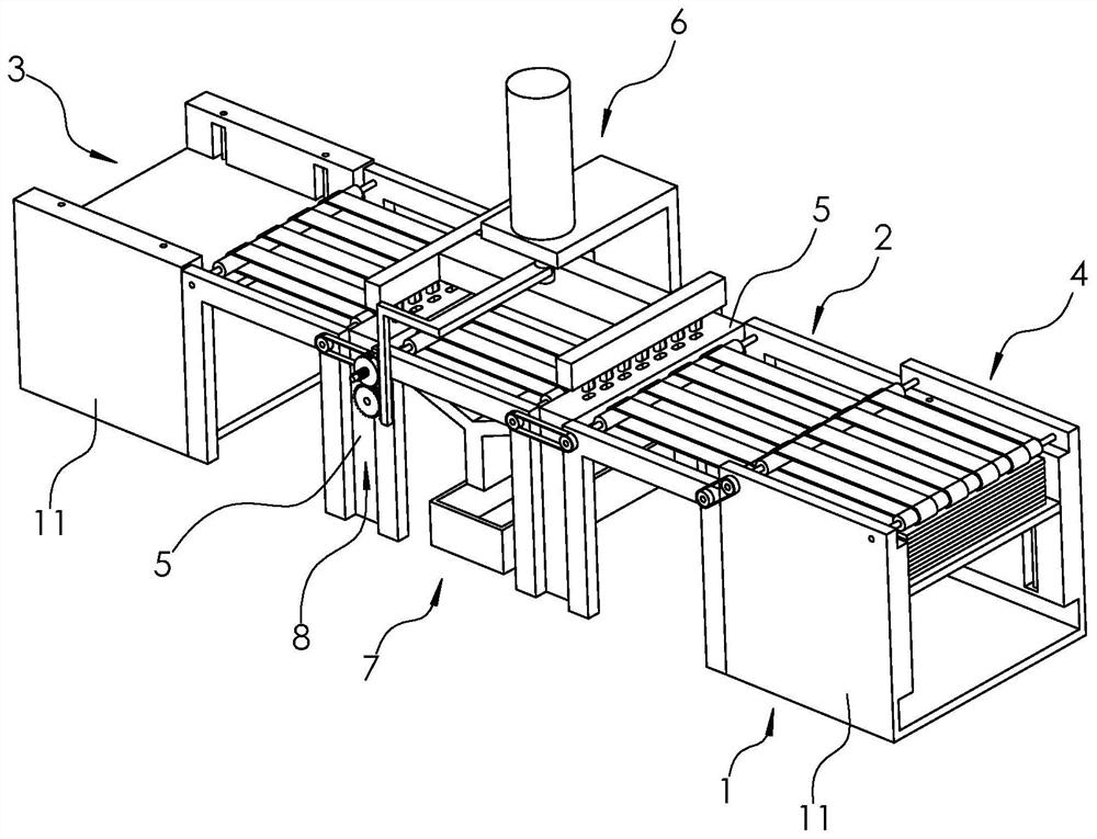
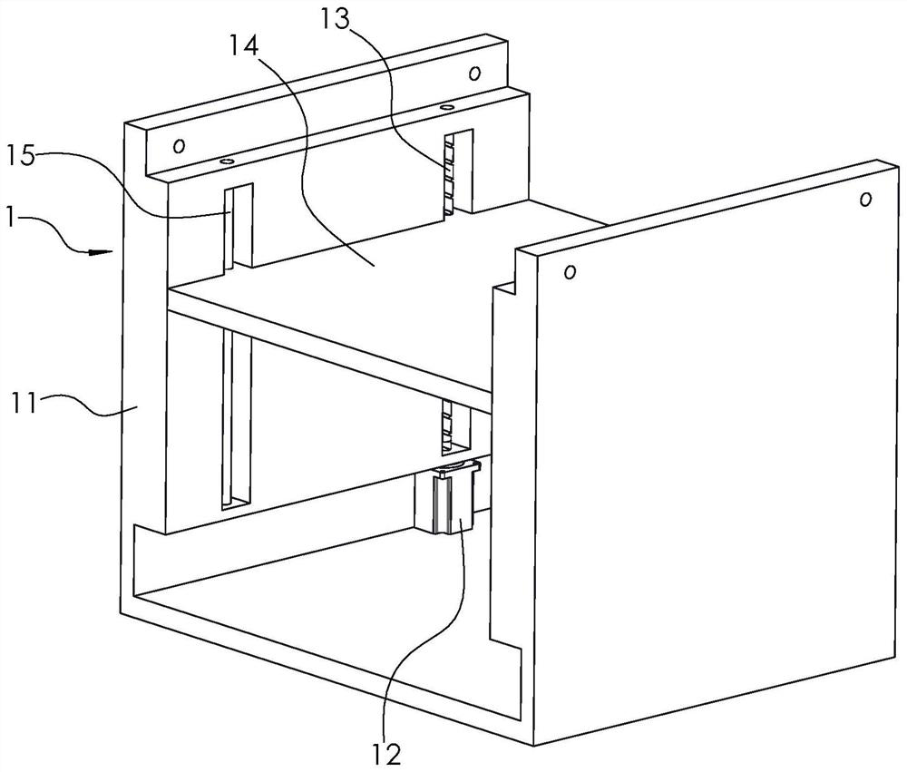
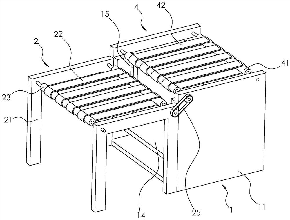
[0035] The following is attached Figure 1-6 The application is described in further detail.

[0036] The embodiment of the present application discloses a sheet metal stamping device. Such as figure 1 As shown, a sheet metal stamping device includes a feeding mechanism 1, three sets of first conveyor belts 2 and a blanking mechanism 3 arranged in sequence along the horizontal direction, and a second conveyor belt 4 is arranged directly above the feeding mechanism 1. Workbenches 5 are arranged between two groups of adjacent first conveyor belts 2 , the same set of stamping mechanisms 6 is arranged directly above the two groups of workbenches 5 , and the same group of collecting mechanisms 7 is arranged directly below the two groups of workbenches 5 . The second conveyor belt 4 is used to load the sheet material on the feeding mechanism 1 onto the first conveyor belt 2, the first conveyor belt 2 is used to transport the sheet material, and the stamping mechanism 6 is used to ...


PUM


Abstract

The invention relates to the technical field of stamping equipment, and particularly relates to a metal plate stamping device. The metal plate stamping device comprises a stamping mechanism and three sets of first conveying belts which are sequentially arranged in the horizontal direction; the arrangement direction of the three sets of first conveying belts is the same as the movement direction of plates on the first conveying belts; a workbench used for supporting the plates is arranged between every two adjacent sets of first conveying belts; the workbenches are provided with row holes; the stamping mechanism comprises a support; the support is provided with a hydraulic cylinder; a piston rod of the hydraulic cylinder extends in the vertical direction and is connected with a connecting frame; the connecting frame is provided with two sets of row stamping units penetrating the corresponding row holes; the row stamping units are located above the workbenches; and the distance between the two sets of row stamping units is equal to odd times of the distance between every two adjacent rows of row holes. The metal plate stamping device can improve the plate stamping efficiency.

Description

technical field [0001] The present application relates to the technical field of punching equipment, in particular to a sheet metal punching device. Background technique [0002] During the assembly process of the forklift roof guard, it is necessary to use plates to connect the various components, and these plates are usually stamped by a punch press. [0003] During the stamping process of the plate, the worker will place the metal plate on the workbench of the punching machine, and the worker will carry out intermittent stamping on the metal plate through the punching machine while pushing the metal plate to move. [0004] Regarding the above-mentioned related technologies, the inventor believes that there are the following defects: in the stamping process of the plate, workers need to control both the feed rate of the plate and the punching machine, which is cumbersome to operate and affects the stamping efficiency of the plate. Contents of the invention [0005] In o...

Claims


Application Information

Patent Timeline
IPC IPC(8): B21D43/12B21D43/22B21D43/00
CPCB21D43/003B21D43/12B21D43/22
Inventor 相光华
Owner 杭州临安荣升机械有限公司
Why Eureka
Try Eureka