Auxiliary welding equipment for petroleum pipeline machining
A technology for auxiliary welding and oil pipelines, used in auxiliary welding equipment, welding equipment, metal processing equipment, etc., can solve problems such as pipeline movement and inconvenient welding
- Summary
- Abstract
- Description
- Claims
- Application Information
AI Technical Summary
Problems solved by technology
Method used
Image
Examples
Embodiment 1
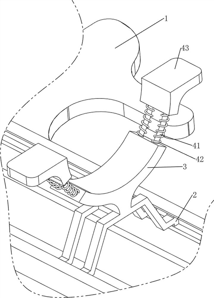
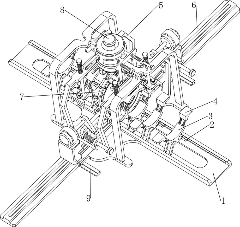
[0028] A kind of auxiliary welding equipment for oil pipeline processing, such as figure 1 As shown, it includes a base plate 1, a slider 2, a first supporting plate 3, an adjustment mechanism 4 and a fixing mechanism 5. The upper part of the base plate 1 is slidingly provided with a plurality of sliders 2, and the upper part of the sliders 2 is provided with a first supporting plate. 3. An adjustment mechanism 4 is provided on the upper part of the first pallet 3, and a fixing mechanism 5 is provided in the middle of the upper part of the bottom plate 1.
[0029] When the user needs to weld the pipes, this equipment can be used. First, the user can move the position of the slider 2 on the bottom plate 1, so that the distance between the sliders 2 is even, and then the user can place the two pipes on the The upper position between the first supporting plates 3 on both sides, and the pipeline is fixed by the adjustment mechanism 4 and the fixing mechanism 5, and then the user c...
Embodiment 2
[0031] On the basis of Example 1, such as Figure 2-3 As shown, the adjustment mechanism 4 includes a first connecting rod 41, a first spring 42 and a first fixing plate 43, and the upper part of the first supporting plate 3 is slidably provided with two first connecting rods 41, and the two first connecting rods 41 A first fixing plate 43 is arranged between them, and two first springs 42 are connected between the first fixing plate 43 and the first supporting plate 3 , and the first springs 42 are sleeved on the first connecting rod 41 .
[0032] After placing the pipe on the first pallet 3, the user can adjust the position of the first connecting rod 41 and the first fixing plate 43 on the first pallet 3 according to the thickness of the pipe, so as to better fix the pipe During this process, the first spring 42 is deformed, and when the user removes the pipe from the first pallet 3, the first spring 42 is completely reset.
Embodiment 3
[0034] On the basis of Example 2, such as Figure 4-7 As shown, the fixing mechanism 5 includes a first fixing column 51, a second fixing plate 52, a second spring 53, a first pressing plate 54, a third spring 55, a screw rod 56, a nut 57 and a handle 58, and the middle of the upper part of the bottom plate 1 is symmetrical A first fixed column 51 is provided in the formula, and two second fixed plates 52 are slidably arranged on the first fixed column 51. A second spring 53 is connected between the second fixed plate 52 and the first fixed column 51. The first pressing plate 54 is slidably connected between the second fixing plates 52, and the third spring 55 is connected between the first pressing plate 54 and the second fixing plates 52 on both sides. Screw rods 56 are movably arranged between the fixing plates 52 , nuts 57 are threadedly connected to the screw rods 56 , and handles 58 are provided at the bottom of the second fixing plates 52 .
[0035] After the pipe is p...
PUM
 Abstract
Description
Claims
Application Information
 - R&D
- Intellectual Property
- Life Sciences
- Materials
- Tech Scout
- Unparalleled Data Quality
- Higher Quality Content
- 60% Fewer Hallucinations
Browse by: Latest US Patents, China's latest patents, Technical Efficacy Thesaurus, Application Domain, Technology Topic, Popular Technical Reports.
© 2025 PatSnap. All rights reserved.Legal|Privacy policy|Modern Slavery Act Transparency Statement|Sitemap|About US| Contact US: help@patsnap.com


