Batch drilling device for PVC boards

A drilling device and plate batch technology, applied in metal processing and other directions, can solve the problems of low drilling efficiency, easy arm soreness, and need for a long time, and achieve the effect of improving drilling efficiency and facilitating drilling work.

Active Publication Date: 2021-06-22
上海京宁环保科技有限公司
View PDF5 Cites 2 Cited by
  • Summary
  • Abstract
  • Description
  • Claims
  • Application Information

AI Technical Summary

Problems solved by technology

[0002] At present, the four corners of the PVC board are generally drilled manually. When manually drilling the four corners of the PVC board, the manual hand-held electric drill is aimed at the PVC board, and then the electric drill is moved downward to drill the PVC board. Hole, so only one hole can be drilled at a time, the drilling efficiency is low, which requires a long time of hand-held electric drill, so the arm is easy to be sore

Method used


Image

  • Batch drilling device for PVC boards
  • Batch drilling device for PVC boards
  • Batch drilling device for PVC boards

Examples


Embodiment 1

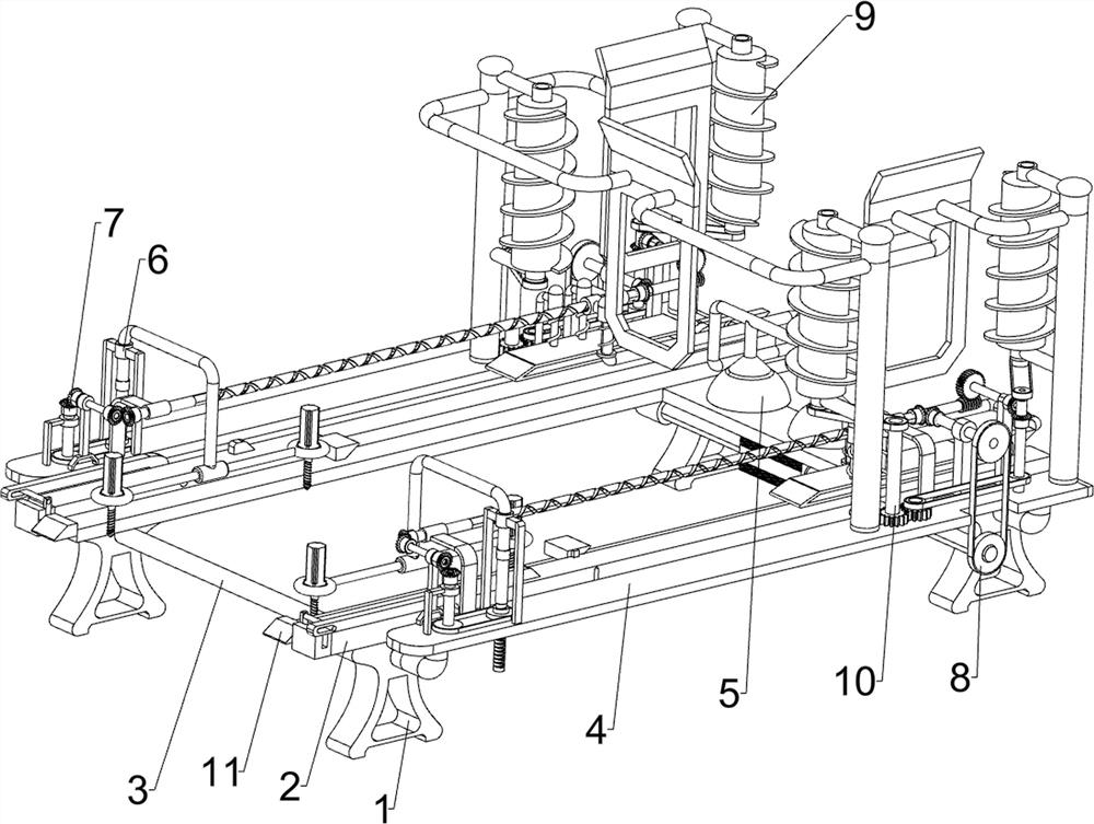
[0027] A kind of PVC board batch drilling device, such as Figure 1-2 As shown, it includes a support foot 1, a slide rail 2, a support rod 3, a feeding plate 4, a feeding mechanism 5 and a drilling mechanism 6. The bottom of the slide rail 2 is symmetrically connected with four support feet 1, and the left two support feet 1 There is a support rod 3 connected between them, and there are two material setting plates 4 symmetrically connected between the support rod 3 and the right leg 1. A feeding mechanism 5 is installed between the material setting plate 4 and the slide rail 2. On the material setting plate 4 Drilling mechanism 6 is installed.

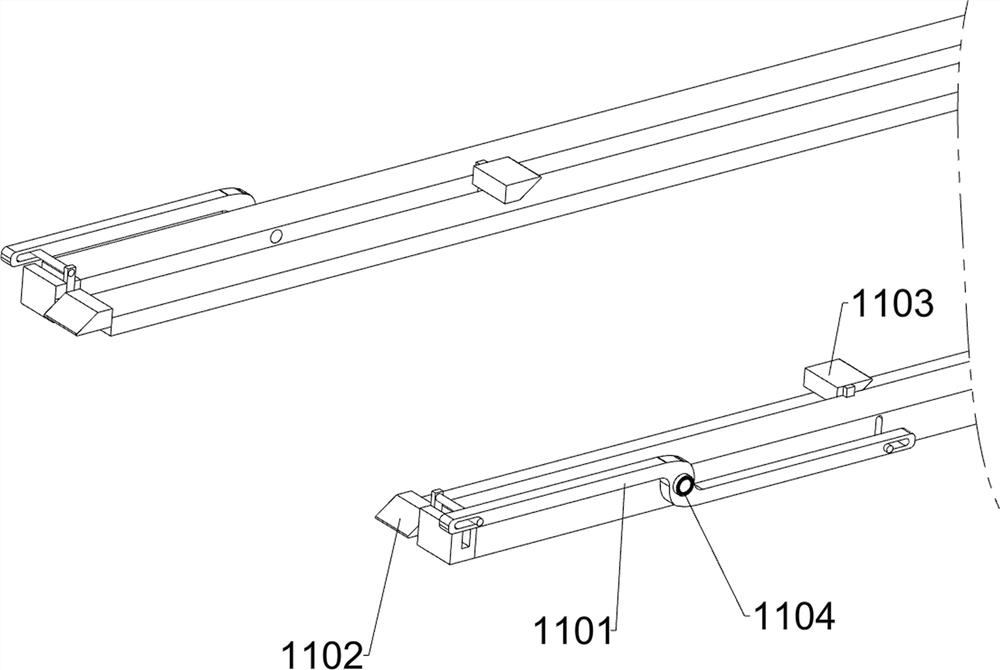
[0028] The feeding mechanism 5 includes a first twist rod 51, a first carriage 52, a first compression spring 53, a suction cup 54, a first wedge 55, a second wedge 56, a first fixing frame 57, a third wedge 58, The second compression spring 59 and the fourth wedge block 510, the top of the material setting plate 4 is rotatably conne...

Embodiment 2

[0032] On the basis of Example 1, such as Figure 1-2 As shown, the first transmission mechanism 7 is also included, and the first transmission mechanism 7 includes a first rotating shaft 71, a first bevel gear set 72, a second rotating shaft 73, a second bevel gear set 74, a second twist rod 75 and a second rotating shaft 75. A belt transmission group 76, the left side of the top of the material plate 4 is rotationally connected with a first rotating shaft 71, the first rotating shaft 71 is located on the left side of the second fixed frame 61, and the first rotating shaft 71 is connected with the first twist rod 51. The first bevel gear set 72, the left side of the top of the material plate 4 is rotationally connected with a second rotating shaft 73, the second rotating shaft 73 is located on the outside of the first rotating shaft 71, and a second rotating shaft 73 is connected with the first rotating shaft 71. The bevel gear set 74, the left part of the material plate 4 is...

Embodiment 3

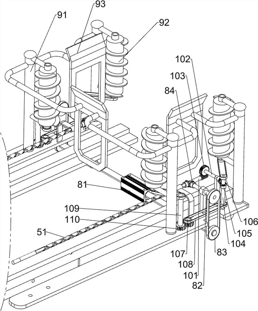
[0036] On the basis of Example 2, such as figure 1 and image 3 Shown, also include unloading mechanism 9, unloading mechanism 9 includes support 91, unloading bar 92 and baffle plate 93, two brackets 91 are connected on the right side of stock plate 4 top, on the bracket 91 rotary type is connected with the bottom Baffles 93 are connected between the material rods 92 and the adjacent brackets 91 .

[0037] Also includes a second transmission mechanism 10, the second transmission mechanism 10 includes a worm 101, a fourth shaft 102, a turbine 103, a fifth shaft 104, a fifth bevel gear set 105, a flat belt 106, a sixth shaft 107, a third Belt transmission group 108, the seventh rotating shaft 109 and the opposite gear group 110, the right end of the first twist rod 51 is connected with a worm 101, the right side of the top of the material plate 4 is rotationally connected with a fourth rotating shaft 102, and the fourth rotating shaft 102 is located on the bracket 91, the fou...


PUM


Abstract

The invention relates to a drilling device, in particular to a batch drilling device for PVC boards, and provides the batch drilling device which are used for the PVC boards, can automatically perform drilling on the PVC boards, can perform batch drilling and can improve the drilling efficiency. The batch drilling device for PVC boards comprises a sliding rail, a material placing plate, a feeding mechanism and a drilling mechanism; four corners of the bottom of the sliding rail are connected with supporting legs, and a supporting rod is connected between the supporting legs on one side; the material placing plate is connected between the supporting rod and the supporting legs on the other side; the feeding mechanism is mounted between the material placing plate and the sliding rail; and the drilling mechanism is mounted on the material placing plate. The feeding mechanism can be driven to work through a power mechanism, the PVC boards can be conveyed to the drilling mechanism through the feeding mechanism, a first transmission mechanism can be driven to work through the feeding mechanism, the drilling mechanism can be driven to work through the first transmission mechanism, and the four corners of the PVC boards can be drilled through the drilling mechanism.

Description

technical field [0001] The invention relates to a drilling device, in particular to a batch drilling device for PVC boards. Background technique [0002] At present, the four corners of the PVC board are generally drilled manually. When manually drilling the four corners of the PVC board, the manual hand-held electric drill is aimed at the PVC board, and then the electric drill is moved downward to drill the PVC board. Holes, so that only one hole can be drilled at a time, and the drilling efficiency is low, which requires a long-term hand-held electric drill, and the arm is prone to soreness. [0003] Therefore need to research and develop a kind of PVC board batch drilling device that can automatically drill to PVC board, can drill in batches, can improve drilling efficiency. Contents of the invention [0004] (1) Technical problems to be solved [0005] In order to overcome the shortcomings of the present invention, the technical problem to be solved by the present in...

Claims


Application Information

Patent Timeline
Patent Type & Authority Applications(China)
IPC IPC(8): B26F1/16B26D7/06B26D5/08B26D7/01
CPCB26F1/16B26D7/06B26D7/0666B26D5/086B26D7/01Y02P70/10
Inventor 舒爱霞
Owner 上海京宁环保科技有限公司
Why Eureka
Try Eureka