Feeding device for 3D printing

A feeding device and 3D printing technology, applied to 3D object support structures, metal processing equipment, manufacturing tools, etc., can solve problems such as insufficient mixing, single type of raw materials, uneven mixing of multiple raw materials, etc.

Pending Publication Date: 2021-06-22
JIANGSU VILORY ADVANCED MATERIALS TECH CO LTD
View PDF7 Cites 4 Cited by
  • Summary
  • Abstract
  • Description
  • Claims
  • Application Information

AI Technical Summary

Problems solved by technology

[0003] 3D printers are equipped with a feeding device. In 3D printing, the types of raw materials are not single. The existing feeding device does not mix a variety of raw materials evenly and insufficiently, which affects the quality of the product. Therefore, there is an urgent need for a 3D printing machine. Printing feeding device to solve the above problems

Method used


Image

  • Feeding device for 3D printing
  • Feeding device for 3D printing
  • Feeding device for 3D printing

Examples


Embodiment 1

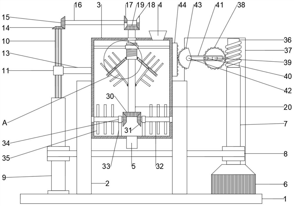
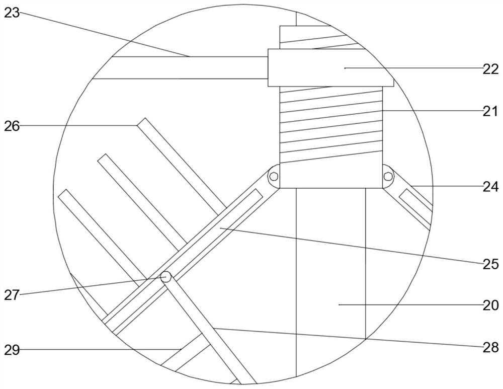
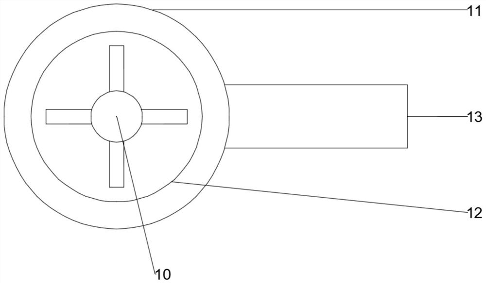
[0023] see Figure 1~4 , in an embodiment of the present invention, a feeding device for 3D printing, including a base 1 and a box body 3, the upper surface of the base 1 is fixedly connected with a support plate 2 symmetrically, and the box body 3 is arranged between the support plates 2 And it is slidably connected with it, the inside of the box body 3 is provided with a first stirring mechanism and a second stirring mechanism, the first stirring mechanism is located above the second stirring mechanism, and a motor 6 is fixedly connected to one side of the upper surface of the base 1, The output end of the motor 6 is fixedly connected with a transmission rod 7, an up and down reciprocating mechanism is arranged above the transmission rod 7, and a drive mechanism is provided on the side of the box body 3 away from the motor 6, and the drive mechanism is a first stirring mechanism Provide power with the second stirring mechanism, the top side of the box body 3 is fixedly conne...

Embodiment 2

[0029] see Figure 5 , on the basis of Embodiment 1, a chute 45 is provided inside the support plate 2, and a slider 46 is slidably connected to the inside of the chute 45, and the slider 46 is fixedly connected to the outer wall of the box body 3, and the slider 46 is fixedly connected to the outer wall of the box body 3. A spring 47 is fixedly connected to the lower surface of the block 46 , and the lower end of the spring 47 is fixedly connected to the lower surface of the chute 45 .

[0030] The working principle of the present invention is: pour the printing material into the box body 3, start the motor 6, the motor 6 drives the transmission rod 7 to rotate, and the belt transmission mechanism 8 drives the card slot column 9 to rotate, and the card slot column 9 drives the card column 10 to rotate , the card column 10 drives the first bevel gear 14 to rotate, the first bevel gear 14 drives the second bevel gear 15 to rotate, the second bevel gear 15 drives the connecting ...


PUM


Abstract

The invention discloses a feeding device for 3D printing. The feeding device comprises a base and a box body, wherein supporting plates are fixedly connected to the upper surface of the base in a bilateral symmetry manner, the box body is arranged between the supporting plates and slidably connected with the supporting plates, a first stirring mechanism and a second stirring mechanism are arranged in the box body, the first stirring mechanism is located above the second stirring mechanism, a motor is fixedly connected to one side of the upper surface of the base, a transmission rod is fixedly connected to the output end of the motor, an up-down reciprocating mechanism is arranged above the transmission rod, a driving mechanism is arranged at the side, away from the motor, of the box body, the driving mechanism provides power for the first stirring mechanism and the second stirring mechanism, one side of the top of the box body is fixedly connected with a feeding port, and the bottom end of the box body is fixedly connected with a discharging port. According to the feeding device, the structure is novel, operation is convenient and fast, raw materials can be fully stirred and uniformly mixed, and the stirring and uniform mixing effect is good.

Description

technical field [0001] The invention relates to the technical field of 3D printing equipment, in particular to a feeding device for 3D printing. Background technique [0002] 3D printer, also known as three-dimensional printer, is a kind of cumulative manufacturing technology, that is, a machine of rapid prototyping technology. It is based on a digital model file, using special wax, powdered metal or plastic and other bondable materials. Print layers of adhesive material to create three-dimensional objects. At this stage, 3D printers are used to manufacture products, which is a technology to construct objects by printing layer by layer. The principle of 3D printers is to put data and raw materials into 3D printers, and the machine will build products layer by layer according to the program. [0003] 3D printers are equipped with a feeding device. In 3D printing, the types of raw materials are not single. The existing feeding device does not mix a variety of raw materials ev...

Claims


Application Information

Patent Timeline
Patent Type & Authority Applications(China)
IPC IPC(8): B29C64/314B29B7/18B33Y40/10
CPCB29C64/314B29B7/18B33Y40/10
Inventor 唐跃跃蒋保林许荣玉叶国晨张柯魏放王玄玄张波俞洋张维
Owner JIANGSU VILORY ADVANCED MATERIALS TECH CO LTD
Why Eureka
Try Eureka