Charging circuit, control method of charging circuit and electric vehicle

A technology of a charging circuit and a control method, which is applied in the field of electric vehicles, can solve the problems of high space occupancy rate of electric vehicles, increase the cost of electric vehicles, and small quantity, and achieve reduction of high-power components, reduction of space occupancy rate, and simple circuit lines Effect

Inactive Publication Date: 2021-06-22
GUANGZHOU CHENGXING ZHIDONG AUTOMOTIVE TECH CO LTD +1
View PDF3 Cites 2 Cited by
  • Summary
  • Abstract
  • Description
  • Claims
  • Application Information

AI Technical Summary

Problems solved by technology

[0002] At present, most of the DC fast charging piles on the market have an output voltage of 500V to 750V. At present, most manufacturers have begun to develop and produce electric vehicles with higher voltage architectures. These electric vehicles with higher voltage architectures are faced with an output voltage of 500V. The DC charging pile cannot be charged, and the DC charging pile with an output voltage of 750V cannot be fully charged
Although there are currently DC charging piles with higher output voltages, their number is small and cannot meet the charging needs of electric vehicles. Therefore, most of them still need to use DC charging piles with an output voltage of 500V to 750V for charging. In order to be able to charge to Higher voltage usually requires a separate booster circuit on the charging circuit
[0003] At present, the booster circuit equipped separately is composed of high-power components. From the perspective of vehicle cost planning, it will undoubtedly increase the cost of electric vehicles; from the perspective of vehicle space design, the general physical area of ​​high-power components is relatively small. Large, which naturally leads to a higher space occupancy rate of electric vehicles

Method used


Image

  • Charging circuit, control method of charging circuit and electric vehicle
  • Charging circuit, control method of charging circuit and electric vehicle
  • Charging circuit, control method of charging circuit and electric vehicle

Examples


Embodiment Construction

[0036] In order to make the above objects, features and advantages of the present invention more comprehensible, the present invention will be further described in detail below in conjunction with the accompanying drawings and specific embodiments. It should be understood that the specific embodiments described here are only used to explain the present invention, only a part of the embodiments of the present invention, not all the embodiments, and are not intended to limit the present invention.

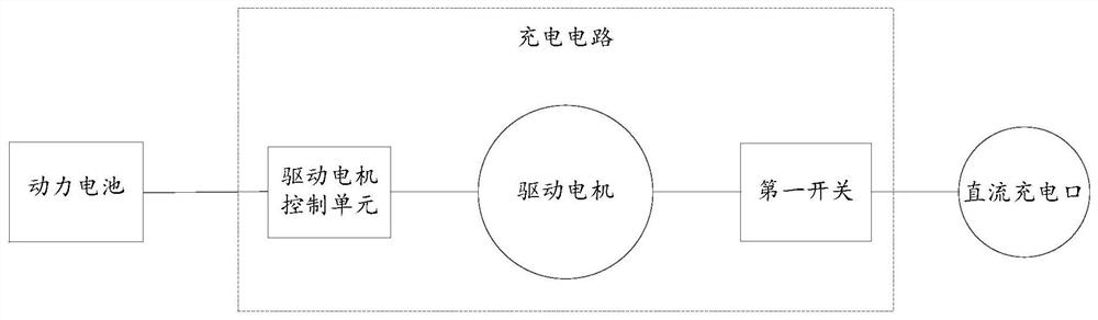
[0037] refer to figure 1 , shows a modular schematic diagram of a charging circuit according to an embodiment of the present invention. The charging circuit includes: a first switch, a driving motor and a driving motor control unit; one end of the first switch is connected to the DC charging port, and the other end is connected to the third winding of the driving motor. Generally, the DC charging port needs to be connected to the charging pile. After all the tests before charging ar...


PUM


Abstract

The invention provides a charging circuit, a control method of the charging circuit and an electric vehicle, and relates to the technical field of electric vehicles, the charging circuit comprises a first switch, a driving motor and a driving motor control unit; one end of the first switch is connected with a DC charging port, and the other end is connected with a third winding of the driving motor; direct current input from the direct current charging port flows to the third winding through the closed first switch; direct current flowing into the third winding flows to the first winding and the second winding of the driving motor; direct current flowing into the first winding and the second winding is boosted by a boosted circuit formed by the first winding, the second winding and the driving motor control unit and then flows to a power battery. High-power parts in the electric vehicle are greatly reduced, the number of components in the whole charging circuit is small, the circuit line is simple, the space occupancy rate is greatly reduced, and meanwhile the cost of the electric vehicle is well reduced.

Description

technical field [0001] The invention relates to the technical field of electric vehicles, in particular to a charging circuit, a control method for the charging circuit and an electric vehicle. Background technique [0002] At present, most of the DC fast charging piles on the market have an output voltage of 500V to 750V, and most manufacturers have begun to develop and produce electric vehicles with higher voltage architectures. These electric vehicles with higher voltage architectures are faced with an output voltage of 500V. The current DC charging pile cannot be charged, and the DC charging pile with an output voltage of 750V cannot be fully charged. Although there are currently DC charging piles with higher output voltages, their number is small and cannot meet the charging needs of electric vehicles. Therefore, most of them still need to use DC charging piles with an output voltage of 500V-750V for charging. In order to be able to charge to Higher voltage usually req...

Claims


Application Information

Patent Timeline
IPC IPC(8): B60L53/22
CPCB60L53/22Y02T10/70Y02T10/7072Y02T90/14
Inventor 张明
Owner GUANGZHOU CHENGXING ZHIDONG AUTOMOTIVE TECH CO LTD
Why Eureka
Try Eureka