
Automobile door driving mechanism

A technology for driving mechanism and car door, which is applied to power control mechanism, wing leaf control mechanism, door/window accessories, etc. Low-noise, reliable results

Pending Publication Date: 2021-06-22
NINGBO XINTAI MACHINERY
View PDF0 Cites 4 Cited by
  • Summary
  • Abstract
  • Description
  • Claims
  • Application Information

AI Technical Summary

Problems solved by technology

At the same time, it also avoids colliding with other obstacles during the process of opening and closing the door, damaging the door, or pinching the hands / feet of the person to cause personal injury; the door is not closed in place and other abnormal situations, most of the conventional car doors are opened and closed manually, and there are The following defects: 1. The conventional mechanical limiter adopts 3 gears, the manual operation force varies greatly between the gears, and the manual force is relatively abrupt when switching between gears, and the hand feeling is poor; 2. The conventional mechanical limiter , In extreme working conditions such as up, down, and side slopes, the door cannot hover, and it will fall and open automatically, which is prone to collision / clamping dangerous accidents; 3. When the door is opened: it hits an external obstacle, damages the door / causes other Accidents; 4. When the car door is closed: ①. It is not closed properly, and it is in a half-locked state. The door is easy to open when driving, causing accidents and affecting personal safety; The electric door mechanism mostly adopts the zipper / rack / hinge shaft type, which has the disadvantages of many parts and complex structures, and takes up a large space, or cannot realize up / down / side slope hovering, etc.

Method used


Image

  • Automobile door driving mechanism
  • Automobile door driving mechanism
  • Automobile door driving mechanism

Examples


Embodiment Construction

[0034] The technical solutions in the embodiments of the present invention will be clearly and completely described below in conjunction with the drawings in the embodiments of the present invention. Apparently, the described embodiments are only some of the embodiments of the present invention, not all of them. Based on the embodiments of the present invention, all other embodiments obtained by persons of ordinary skill in the art without making creative efforts fall within the protection scope of the present invention.

[0035] In the description of the present invention, it should be understood that the terms "center", "transverse", "longitudinal", "front", "rear", "left", "right", "upper", "lower", "vertical The orientations or positional relationships indicated by "straight", "horizontal", "top", "bottom", "inner" and "outer" are based on the orientations or positional relationships shown in the drawings, and are only for the convenience of describing the present inventio...


PUM


Abstract

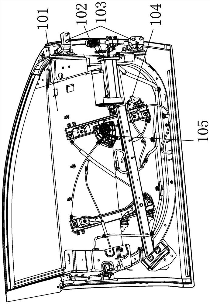
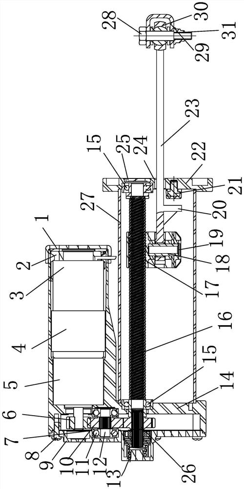
The invention belongs to the technical field of automobile doors, and provides an automobile door driving mechanism. The automobile door driving mechanism is installed and fixed on an automobile door assembly and comprises a main body pipe, a lead screw assembly, a pull rod assembly, a transmission assembly and a motor assembly, wherein a clutch brake assembly is installed on the motor assembly, when the automobile door driving mechanism receives an ECU controller door opening or closing signal, the motor assembly runs and is transmitted to the lead screw assembly through the transmission assembly to rotate, the pull rod assembly is pushed to do linear motion, and therefore the pull rod assembly generates pushing force and transmits the pushing force to the automobile door to open or close the automobile door. The automobile door driving mechanism has the advantages of simple structure and reliable function, the size is small, installation is convenient, running noise is low, the automobile door can be electrically and automatically opened and closed, in the manual state, the door is slowly opened and closed, the manual power is light, the door is rapidly opened and closed, and a tail door is automatically opened and closed in a follow-up mode.

Description

technical field [0001] The invention belongs to the technical field of automobile doors and relates to an automobile door driving mechanism. Background technique [0002] With the development of automobile automation and intelligence, the demand for automatic door opening and closing mechanisms of automobiles is increasing, which greatly improves the user's car experience and enhances the convenience of users. The mechanism has high practicability, realizes the automatic opening and closing of the car door, and is convenient for people to travel. At the same time, it also avoids colliding with other obstacles during the process of opening and closing the door, damaging the door, or pinching the hands / feet of the person to cause personal injury; the door is not closed in place and other abnormal situations, most of the conventional car doors are opened and closed manually, and there are The following defects: 1. The conventional mechanical limiter adopts 3 gears, the manual ...

Claims


Application Information

Patent Timeline
Patent Type & Authority Applications(China)
IPC IPC(8): E05F15/622E05F15/40E05F15/70E05F5/06
CPCE05F5/06E05Y2900/531E05F15/40E05F15/622E05F15/70
Inventor 杨琪沈宝良
Owner NINGBO XINTAI MACHINERY
Learn More